
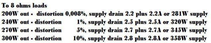
Byron's 300VA transformer will result in a perfect 200 plus 200 watts amplifier
With a very low harmonic distortion.
As i can see, his decisions about are very clever, he may work with 8 ohms (standard impedance, easy to find drivers to match that power) and can search for soft to move speakers, high compliance woofer drivers, 12 or 15 inches units that may fit so good as a glove can fit into your fingers.
Having 200 watts of power, working in a very low distortion range, 60 percent of the power will go to the woofer (musical standard ratio), so, 120 watts RMS will go to woofer...he may find units that are easy to move (not hard centering spiders, not a hard rubber suspension) with 250 watts (IHF) that will be perfect for him... he will save money and will optimize sonics this way.
60 watts (120 IHF) midrange drivers and 20 watts tweeters (40 IHF) will work great too.
Eletrolytic condenser bank can be from 10.000uf plus 10.000uf to 15.000 to 15.000uf to each channel, and this will save money too ... his 20 thousand plus 20 thousand may be good too.
Heatsinks will not be that big, and this will allow him to use two supplies, and this is excellent!
I do think his decision was perfect, or at least matched my own decisions about.... i am using the MKII Supercharged, in that range of power too, and i think that range of power was a perfect decision..not bigger or smaller than we need in the real world... and the MKIII can operate into this power with a lower distortion you can have with the MKII Supercharged.
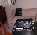
Picture shows one of my Supercharged units.. i have three, sometimes i connect them together in a pile, then i have stereo bass, mids and treble channels having separated knobs to control volume for these three semi audio bands.
If he guy does not select high power drivers, these ones used together class D automotive amplifiers, then he will have good sound..... car drivers are hard to move, they need 500 watts RMS or more to be efficient... at least Brazilian popular drivers are this way... exception is Bravox and Selenium.
regards,
Carlos
With a very low harmonic distortion.
As i can see, his decisions about are very clever, he may work with 8 ohms (standard impedance, easy to find drivers to match that power) and can search for soft to move speakers, high compliance woofer drivers, 12 or 15 inches units that may fit so good as a glove can fit into your fingers.
Having 200 watts of power, working in a very low distortion range, 60 percent of the power will go to the woofer (musical standard ratio), so, 120 watts RMS will go to woofer...he may find units that are easy to move (not hard centering spiders, not a hard rubber suspension) with 250 watts (IHF) that will be perfect for him... he will save money and will optimize sonics this way.
60 watts (120 IHF) midrange drivers and 20 watts tweeters (40 IHF) will work great too.
Eletrolytic condenser bank can be from 10.000uf plus 10.000uf to 15.000 to 15.000uf to each channel, and this will save money too ... his 20 thousand plus 20 thousand may be good too.
Heatsinks will not be that big, and this will allow him to use two supplies, and this is excellent!
I do think his decision was perfect, or at least matched my own decisions about.... i am using the MKII Supercharged, in that range of power too, and i think that range of power was a perfect decision..not bigger or smaller than we need in the real world... and the MKIII can operate into this power with a lower distortion you can have with the MKII Supercharged.
Picture shows one of my Supercharged units.. i have three, sometimes i connect them together in a pile, then i have stereo bass, mids and treble channels having separated knobs to control volume for these three semi audio bands.
If he guy does not select high power drivers, these ones used together class D automotive amplifiers, then he will have good sound..... car drivers are hard to move, they need 500 watts RMS or more to be efficient... at least Brazilian popular drivers are this way... exception is Bravox and Selenium.
regards,
Carlos
Attachments
Last edited:
I also plan to use 45+45/300VA power supplies per channel. This will also permit using only 3 output pairs in place of 5, which will cut down $18USD per amp board (so $36 of saving for a stereo amp).
Carlos, can the inductance be put outside the board? It's gonna be too tight to fit it seems.
Martin.
Carlos, can the inductance be put outside the board? It's gonna be too tight to fit it seems.
Martin.
How to wire you input volume potentiometer in your MKIII Hx
Here you have a video explaining.
Read the description box below your video (show more) as you will have extra instructions about how to proceed if you decide to use high level output preamplifiers:
MKIII Hx input volume control connection - YouTube
regards,
Carlos
Here you have a video explaining.
Read the description box below your video (show more) as you will have extra instructions about how to proceed if you decide to use high level output preamplifiers:
MKIII Hx input volume control connection - YouTube
regards,
Carlos
Last edited:
Actually, just lucky, apparently.As i can see, his decisions about are very clever
 I have these because I bought them from the swap meet for another project, then found they wouldn't work for that PS.
So my filter caps are overkill? Oh well, maybe I'll take some for another project some day.Eletrolytic condenser bank can be from 10.000uf plus 10.000uf to 15.000 to 15.000uf to each channel, and this will save money too ... his 20 thousand plus 20 thousand may be good too.
Really? That good to know! I was planning on a chassis with big heatsinks - the kind where the entire side panels are fins facing outward - and was having a difficult time finding a chassis into which everything would fit. I was considering an external PS. It's good to know I can free up some space inside my amp.Heatsinks will not be that big, and this will allow him to use two supplies, and this is excellent!
PCB mounting holes are too small!
I just found that the four holes in the corners are too small to fit a #6-36 machine screw through, which is a common size (the only size?) for PCB mounting hardware. I found that a 5/32" and a 9/64" bit both widen the holes to just the right size for #6-32 machine screws. This is probably my mistake. The PCB manufacturer would not accept the original drill files, and I had to change them, as Alex was on vacation. I apologize for the inconvenience, but it's just that - an inconvenience.
I just found that the four holes in the corners are too small to fit a #6-36 machine screw through, which is a common size (the only size?) for PCB mounting hardware. I found that a 5/32" and a 9/64" bit both widen the holes to just the right size for #6-32 machine screws. This is probably my mistake. The PCB manufacturer would not accept the original drill files, and I had to change them, as Alex was on vacation. I apologize for the inconvenience, but it's just that - an inconvenience.
I'll post them Tuesday
There is very little difference between the board and schematic posted in post #14 and the final version. In fact, I think the only difference is the location of R15 (330ohm, 1/4W) but I'll post the new one Tuesday.
My parts list has undergone some tweeks, but has not changed much. I'll post that Tuesday too.
Has anybody used this softstart already? Looks like a bargain to me, no need to assemble anything, just plug it in...
Connexelectronic
Oh and they even have speaker protection boards... cheap enough to me!
http://connexelectronic.com/product...ducts_id/71?osCsid=cd8nalvtr6vsops9ngunsa7370
Martin.
Connexelectronic
Oh and they even have speaker protection boards... cheap enough to me!
http://connexelectronic.com/product...ducts_id/71?osCsid=cd8nalvtr6vsops9ngunsa7370
Martin.
Last edited:
Updated parts list
I just want be sure everyone knows this is not the "official" parts list. It has not been checked and approved by the designer, Carlos. There may be mistakes or bad decisions. It is simply what I have purchased. I have not even finished building the board with this parts list.
-Byron
I just want be sure everyone knows this is not the "official" parts list. It has not been checked and approved by the designer, Carlos. There may be mistakes or bad decisions. It is simply what I have purchased. I have not even finished building the board with this parts list.
-Byron
Attachments
 with all these matched parts...
When will there be an official parts list ..?
That is Carlos' decision, as he is the designer.
With the exceptions of C15 and C16, which I have made a note of on the schematic, there are no discrepancies between the board's silkscreen and the schematic. Unless I missed something . . .are the ones on the boards correct ?
- Status
- Not open for further replies.
- Home
- Amplifiers
- Solid State
- Dx Blame MKIII-Hx - Builder's thread