Input cap 1 uf or 2 uf ?, c15/16 on the board is the correct value..?
Input cap - good question. I didn't notice that one. Carlos wrote the schematic, and Alex made the silkscreen, so I would go with the schematic. But maybe wait for Carlos to weigh in. Same with C15
C16 - These are really supplemental power supply filter caps, so there is no right value. If your power supply is smooth enough, you can even skip these.
-Byron
Byron, I made my own list. So it's easy for me to spot mistakes by comparing mine and yours (2 persons rarely makes mistakes at the same place ") )
)
I think you got the C06 wrong, on the schematic it shows as a 100uF (not 47uF)
For T5, you selected MJL15032 along with a value for R21 of 680R although the stated components are MJL15030 and R21=1.2K Maybe you want to double-check this.
For R26's you selected a rating of 3W, the point has been debated in another post showing that the way to go is 5W.
As mentionned by a.wayne, the latest thing we want is to smoke our project!
Question: enamelled copper wire costs a lot, would it be possible to use some already-made toroid inductors like the Bournes 2100HT-2R2-RC instead? They only cost a few bucks each...
Martin.
)I think you got the C06 wrong, on the schematic it shows as a 100uF (not 47uF)
For T5, you selected MJL15032 along with a value for R21 of 680R although the stated components are MJL15030 and R21=1.2K Maybe you want to double-check this.
For R26's you selected a rating of 3W, the point has been debated in another post showing that the way to go is 5W.
As mentionned by a.wayne, the latest thing we want is to smoke our project!
Question: enamelled copper wire costs a lot, would it be possible to use some already-made toroid inductors like the Bournes 2100HT-2R2-RC instead? They only cost a few bucks each...
Martin.
Last edited:
Thank you Maritn!
One of my hopes, when posting this, was that people would go through it and find mistakes and make suggestions.
One of my hopes, when posting this, was that people would go through it and find mistakes and make suggestions.
Yep, my mistake.I think you got the C06 wrong, on the schematic it shows as a 100uF (not 47uF).
Yes. I went with what was on the silkscreen, which I now see is inconsistent with the schematic. I see the only difference between MJE15030 and MJE15032 is that MJE15032 is rated for 250V, while MJE15030 is rated for 150V. MJE15032 is already soldered in to place, so I'll leave it, but I think I'll change R21.For T5, you selected MJL15032 along with a value for R21 of 680R although the stated components are MJL15030 and R21=1.2K.
I had forgotten about that post. Thanks.For R26's you selected a rating of 3W, the point has been debated in another post showing that the way to go is 5W.
I don't see why not if you can make it fit. Or you could salvage some wire from any speaker X-overs you have lying around.Question: enamelled copper wire costs a lot, would it be possible to use some already-made toroid inductors like the Bournes 2100HT-2R2-RC instead? They only cost a few bucks each...
This is getting very confusing for me, could we please get this all rectified by having the Corrected values and parts necessary for construction , noted by doing an revised BOM/Schematics....?
I agree with that,
I think everyone wants to build a good amplifier, and let's not go cut down on the components.
What brand resistors and capacitors are good for this amplifier?
I suppose the 10000uF is very important.
Please make a good BOM list for this amplifier.
Regards,
Rudy
Junie has posted (then retired?) a very interresting thing... T5 connection is wrong if MJE15030-MJE15032 (BCE) is selected... BD139 (ECB) has the correct pinout.
If so, R21 should be of 2.7K
Watch-out!
Forget that, I was wrong. The trimpot and R21 are swapped on the PCB and will have no incidence on the bias adjustment. The pinout is correct for the MJE15032.
BD139 will not be adequate.
My bad.
Forget that, I was wrong. The trimpot and R21 are swapped on the PCB and will have no incidence on the bias adjustment. The pinout is correct for the MJE15032.
BD139 will not be adequate.
My bad.
Hi Martin, i figured that out too so i deleted my post to avoid confusion.
Is it required to have an official part list anyway? Some parts will be substituted by others depending on availability around the globe. As an amplifier plan suggested by a hobbyist to other hobbyists, part of the hobby is building our own BOM. Don't we say that "the fun of traveling is not the destination but the trip itself"?
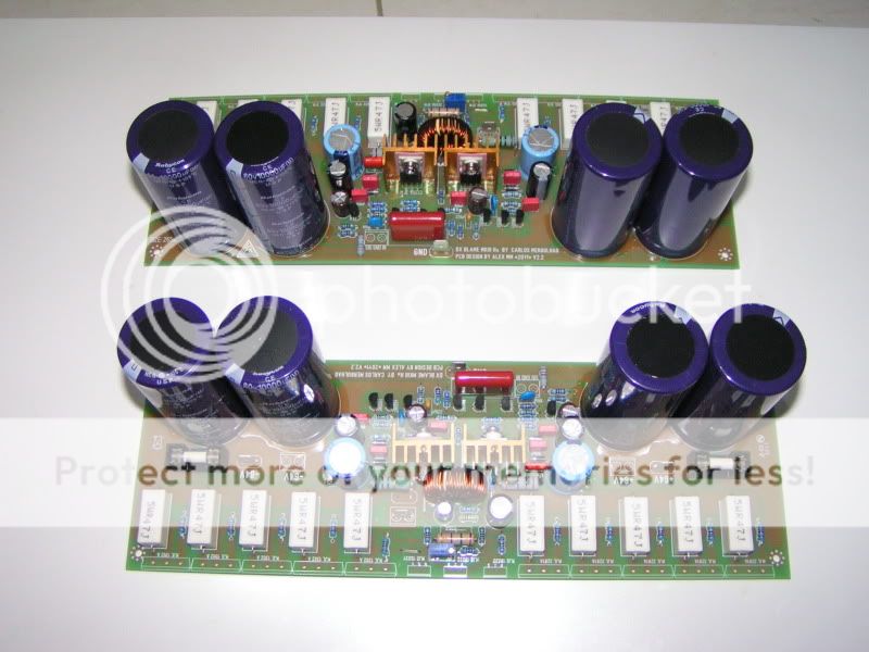
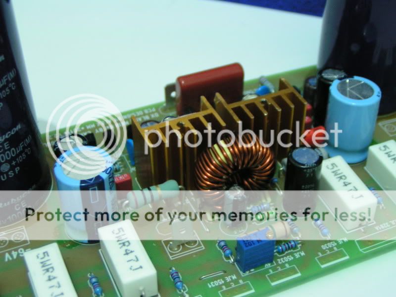
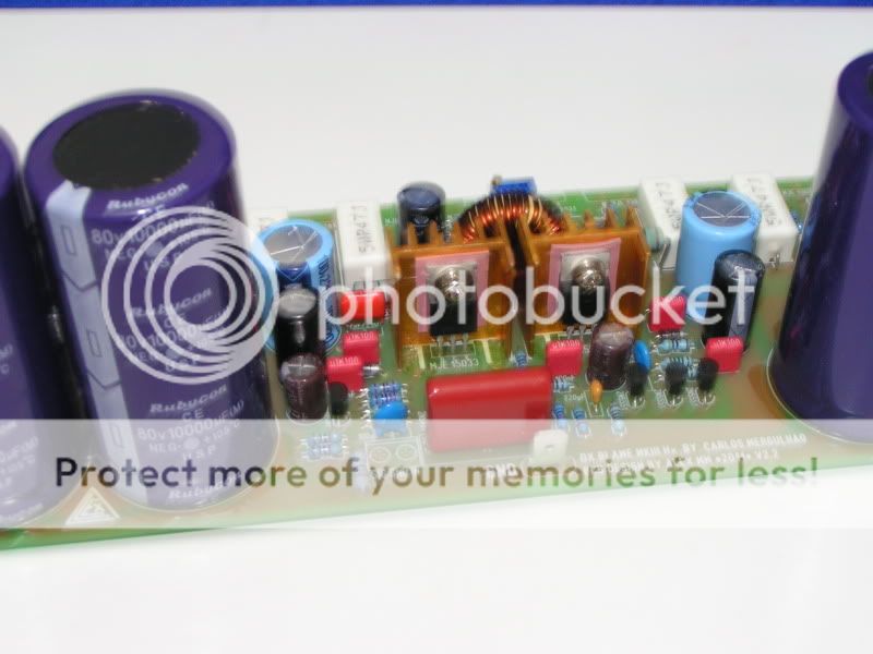
For anyone interrested, here's my own BOM. It's my own variant; amp will be dual-mono, 45+45VAC/300VA each side, 3 output pairs. Confirmed by the father of this project: it will still sound good
For anyone interrested, here's my own BOM. It's my own variant; amp will be dual-mono, 45+45VAC/300VA each side, 3 output pairs. Confirmed by the father of this project: it will still sound good
Attachments
I would not wait for a BOM
The only person qualified to make a really definitive/authoritative BOM is the designer, Carlos. I could be wrong, but I don't think he's interested in putting together such a list. The schematic and all of Carlos' U-tube videos should suffice.
I think we are currently proceeding the best way possible - by posting our own parts lists and commenting on them, like the errors Martin found.
Has anyone completed and tested a board yet?
If anyone has, it would be great if they posted what parts they used. I just got what I think is the last of the parts I need and I'll be busy soldering away. One power supply is built and tested, so hopefully, I'll soon have a functional amplifier to validate the parts list I posted.
Byron, post96:
don't power up just yet.
Go back and review the resistors across the PSU supply rails.
2k0 dissipates ~ 60V^2 / 2k = 1W8.
The pair of 2k bleeders will dissipate an extra 3W6 inside the case.
The 2k bleeders will draw an extra 30mAdc from the PSU. This will increase the ripple voltage on the PSU and gives no performance gain to the amplifier.
The 500r for the LED dissipates ~[2*60 - 2]^2 / 500 = 28W. Fortunately the LED blew up long before the resistor set fire to the amplifier.
Last edited:
Andrew have made interesting suggestion Byron
Take a good look about his points...i have not tested because extremely busy i am... i am doing exercises all day long..outside home...i am gaining weight even after gastric bypass and i am in panic... i am in a struggle to loose weight and using bike almost all day long.
Please, about any doubt, post direct questions and as soon as possible i will answer you.
regards,
Carlos
Attachments
Last edited:
Take a good look about his points...i have not tested because extremely busy i am... i am doing exercises all day long..outside home...i am gaining weight even after gastric bypass and i am in panic... i am in a struggle to loose weight and using bike almost all day long.
Please, about any doubt, post direct questions and as soon as possible i will answer you.
regards,
Carlos
Focus on your food groups , it's not just about the exercise, you have to change your diet and amt..
Thank you Andrew
Hi Andrew,
Thank you so much for checking my work for me. So, you actually built it? I just now put in the LED and its 500ohm resistor and the 500ohm resistor started slowly smoking. So you think 1Kohm and 500ohm are too low values? Another poster thought 2K ohm was too much for a bleeder. I have a nice article by Elliott Sounds lab about linear PS design which I've been too lazy to read carefully.
Elliott Sound Products - Linear Power Supply Design I'll have to read it again and o the math this time. I will say that the LED stayed on for a looooooooong time after switching the power off.
I do have a question: I measured the VDC from positive-ground at +58V, and negative-ground at -58V. So I figure the voltage across positive to negative, skipping ground, should be 116 VDC, but it's almost nothing, ~0.01V, both with and without a 2Kohm, 3W resistor across them (I've heard that some voltmeters will not measure voltage accurately unless a little bit of current is running). If this measurement is correct, how does 0.01V cause a 500ohm resistor to smoke? Is my voltmeter working correctly?
Byron, post96:
don't power up just yet.
Go back and review the resistors across the PSU supply rails.
Hi Andrew,
Thank you so much for checking my work for me. So, you actually built it? I just now put in the LED and its 500ohm resistor and the 500ohm resistor started slowly smoking. So you think 1Kohm and 500ohm are too low values? Another poster thought 2K ohm was too much for a bleeder. I have a nice article by Elliott Sounds lab about linear PS design which I've been too lazy to read carefully.
Elliott Sound Products - Linear Power Supply Design I'll have to read it again and o the math this time. I will say that the LED stayed on for a looooooooong time after switching the power off.
I do have a question: I measured the VDC from positive-ground at +58V, and negative-ground at -58V. So I figure the voltage across positive to negative, skipping ground, should be 116 VDC, but it's almost nothing, ~0.01V, both with and without a 2Kohm, 3W resistor across them (I've heard that some voltmeters will not measure voltage accurately unless a little bit of current is running). If this measurement is correct, how does 0.01V cause a 500ohm resistor to smoke? Is my voltmeter working correctly?
was your voltage meter set for measuring AC or DC voltage?
Now back to that slightly smoking resistor !
the LED has a Vf~2V.
The 116Vdc across the supply is split between the resistor and the LED. The resistor sees 116-2 ~114Vdc.
The resistor dissipation is 114^2 / 500 or approximately 26W, only "slightly smoking"?
The current passing through the LED is ~=114/500 = 0.228A or about 228mA. What is the maximum current for the LED?
Current limiting Resistor calculator for leds
LED current:
20mA will work for most regular LED's.
Superbright LED's can go from 30mA to several Amps.
In Byron's PSU he need a 6Kohm 2W resistor in series to LED?
LED current:
20mA will work for most regular LED's.
Superbright LED's can go from 30mA to several Amps.
In Byron's PSU he need a 6Kohm 2W resistor in series to LED?
Last edited:
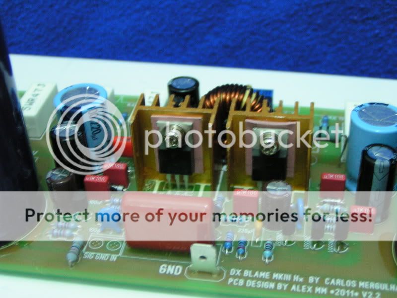
While populating one of my boards I made notes of mistakes I made or things I would have done differently. Here they are:
Junie: Thanks for the link to the cool LED resistor calculator. It won't work for rail voltages >32V, but even if my rails were only 32V I would need 3X the resistance I currently have! Knowing this I'll estimate ~2500ohms.
Sandbasser: I posted a schematic of my power supply, and people were kind enough to comment on it. There is no LED on the board.
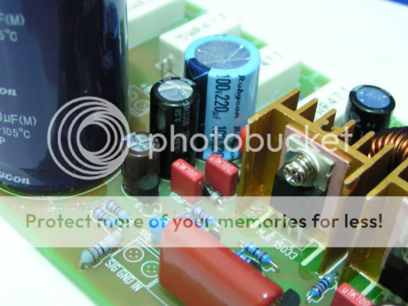
- C08, C11 and C15 are too close together for the caps I chose to fit nicely, but they're reeeeeeely close. My solution was to insert the middle one last, and move it to the left just a bit, which requires raising it off the board a few mm and bending the leads.
- For R10 and R19 I chose 1/2W. I don't remember why Maybe I had a good reason but regardless, they are too long and the leads too thick.
- R22 should be 4.7ohm, not 2.7ohm.
- The leads for C09 are further apart than the holes in the board.
- I don't like the terminal blocks I chose. The wire slips out with a gentle tug.
- The ceramic disk capacitors I chose for most on the non-polar caps have their leads a little too far apart. I like the block-shaped caps Junie showed in his photos.
Junie: Thanks for the link to the cool LED resistor calculator. It won't work for rail voltages >32V, but even if my rails were only 32V I would need 3X the resistance I currently have! Knowing this I'll estimate ~2500ohms.
Sandbasser: I posted a schematic of my power supply, and people were kind enough to comment on it. There is no LED on the board.
Vsupply = Vled (Vf) + Vresistor.LED resistor calculator. It won't work for rail voltages >32V,
If you want 12mA through the LED then you turn the equation around to get:
Vresistor =Vsupply -Vled = 116 -2 = 114Vdc
Vresistor = Rresistor * Iresistor (=Iled) = 114V
rearrange again:
Rresistor = 114 / Iresistor = 114 / 0.012 = 9500. Use 10k
If you require more LED current then substitute the alternative value for 0.012 in that last equation.
If you insert a high value Zener in series with the LED, then you can manipulate the brightness of the LED as supply voltage varies.
Last edited:
- Status
- Not open for further replies.
- Home
- Amplifiers
- Solid State
- Dx Blame MKIII-Hx - Builder's thread