
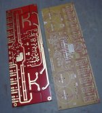
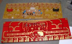
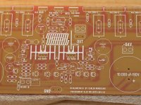
They're the same boards. Some changes to the silkscreen. Junie's came from me. Yours presumably came from Patrick.The boards Junie got are marked V2.2 and the ones I got are Rev 2.0... What are the differences? They're from two different orders?
Martin.
My progress
OK. If Junie is going to show off photos I'll show off mine But my camera is not nearly as nice as is Junie's.
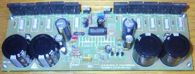
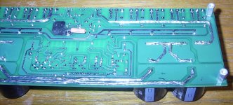
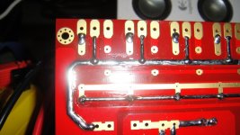
I'm still waiting for those heatsinks I ordered weeks ago! I soldered 14awg wire to the high-current carrying tracks.
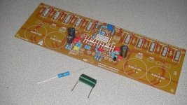
OK. If Junie is going to show off photos I'll show off mine
But my camera is not nearly as nice as is Junie's.I'm still waiting for those heatsinks I ordered weeks ago! I soldered 14awg wire to the high-current carrying tracks.
Attachments
OK. If Junie is going to show off photos I'll show off mine
I'm still waiting for those heatsinks I ordered weeks ago! I soldered 14awg wire to the high-current carrying tracks.
Hello Byron,
I thought about that, adding to the power traces ......What value inductor are you using in the output , where did you get it ..?
Not only output power transistors, but also drivers
and the thermal sensor (bias adjustment transistor) will need insulators, plastic washers, nut and screw.
I suppose you all know that .... but is not that bad to remind you about.
There are silicon pads, looks alike rubber, good thermal conductor and bad electricity conductor, also Mica and also Ceramics.
I do think Mica is the strongest one, you cannot smash it if you tight your screw in excess... the silicon pad, this rubberized thing (looks alike) can be smashed and produce short circuits.
Computer junk supplies have insulators, washer, nuts and bolts if you do not want to order from supplier.
When using Mica is a good idea to use thermal grease.... i do think the silicon pad does not need thermal grease.
Watch your stand by current monitoring your power emitter resistors, try to adjust in order to have less than one milivolt there to avoid excessive waste of energy and heat... the amplifier when using good heatsinks, thermal grease and good ventilation use not to reach 60 degrees celsius when operating 200 watts average.
1 milivolt when the resistance is 0.22 ohms (as an example) results in 4.5 miliamps to each power transistor.... this represents 300 miliwatts of power dissipation to each transistor in stand by mode.... we have 10 power transistors, so we gonna have 3 watts of power dissipation... when using good heatsinks you may have heatsinks with 2 or 3 degrees above environment temperature...so.... will be cool in stand by mode or when listing low volume, at night..with 1 to 2 watts to each channel.
regards,
Carlos
I thought about that, adding to the power traces ......What value inductor are you using in the output , where did you get it ..?
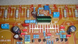
I decided the inductor value was not very important. I wound my own with magnet wire, then covered it with heat shrink tubing to keep it from uncoiling. I tried to use Dayton's WT3 to measure it, but its lower limit is 50uH, so I only know the inductance is <50uH.
I recall Alex writing that he left some tracks exposed so we could tin them. Adding wire is just overkill. My only advice is to tin the tracks after you add all the components.
To use or not to use preamplifier with Dx amplifiers
My personal, subjective, point of view:
Dx Amp... to use or not to use pré amplifier - YouTube
regards,
Carlos
My personal, subjective, point of view:
Dx Amp... to use or not to use pré amplifier - YouTube
regards,
Carlos
Hi guys!
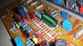
I'm putting the parts little bit by little bit at the time and I think it looks great, don't mind the air coil inductor y like green lol thank to destroyer x, meanman64 and Alex all the people involve, muchas gracias de aqui de Puerto Rico.
I'm putting the parts little bit by little bit at the time and I think it looks great, don't mind the air coil inductor y like green lol thank to destroyer x, meanman64 and Alex all the people involve, muchas gracias de aqui de Puerto Rico.
Attachments
Mr Junie what TV set did you get that coil out of? Evette
Hello joe, I salvage that from the junk SMPS of Sanyo projector PLC-XF46
Varga,
why have you used imageshack to download over 3MB of info for those 5 pics?
Use the attach and let DIYaudio store these high quality pics at a sensible resolution that shows what we need to see.
Mods,
just when are you going to stop this remote server download nonsense?
why have you used imageshack to download over 3MB of info for those 5 pics?
Use the attach and let DIYaudio store these high quality pics at a sensible resolution that shows what we need to see.
Mods,
just when are you going to stop this remote server download nonsense?
Don't use a remote server to store your pics. If they are important and useful enough for us to see them, then it is just as important that we can see them in 1years time or 10years time.
Image Shack and you and your subscription might be long gone.
There are a wide range of acceptable image sizes and resolutions and compressions that DIYaudio accepts. DIYaudio will store these for you. But to aid Members who don't have fast broadband or maybe no Broadband at all, please keep the bit rate of your pics as small as possible and yet gives a good pic we can all appreciate. 1600pixels wide is not required for what you have posted.
This is my Hobby Horse. You can ignore my rants if you choose. But please consider the other 100,000 Members that might want to see your pics in the future.
- Status
- Not open for further replies.
- Home
- Amplifiers
- Solid State
- Dx Blame MKIII-Hx - Builder's thread