I have just completed the Piersma inverted Jfet version. Everything looks and sounds ok so far. the only thing I see is I have 30mvdc at the output. Is this too high? I did not try to match any semi's. Isn't this usually a mismatch at differential front end of SK170's? Is there a way to add resistance to one of the bases to get closer match?
Mismatch jfet at LTP location could be the cause of your problem since you weren't match anything. I think 30mV is a bit too high for my taste. You can check Vgs of the jfet to confirm. But it still sound ...
I'm not sure about add resistance to get closer match but matching n-jet sound more easier to me. With close matched jfet and everything ok, you can have about 1-3mV DC offset.
How Jfet version sounded? I'm curious ...
Yes certainly, and to arrive at only 30mV offset without matching requires more than a bit of luck, given the dispersion of jFETs....Mismatch jfet at LTP location could be the cause of your problem since you weren't match anything.
It is of course the best method, but to achieve 1~3mV OS, a largish sample will have to be tested...I'm not sure about add resistance to get closer match but matching n-jet sound more easier to me.
With close matched jfet and everything ok, you can have about 1-3mV DC offset.
Adding resistance is probably not the best of ideas, since it will introduce asymmetries.
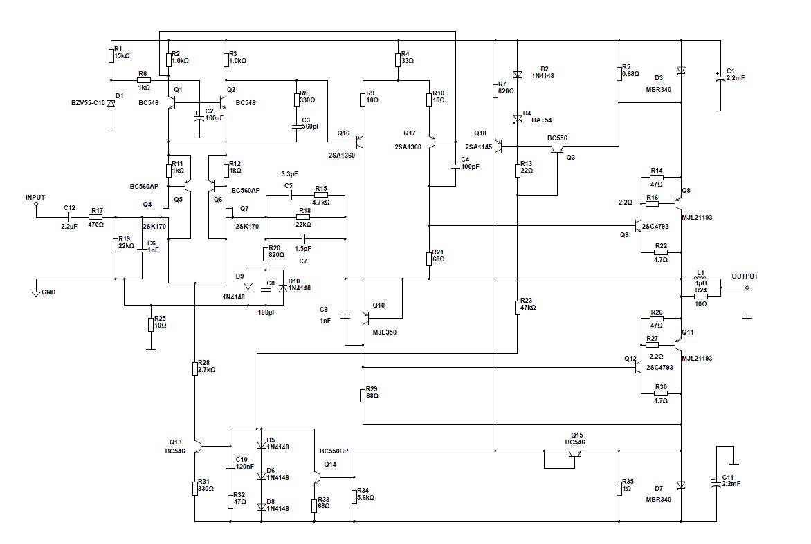
My preferred method would be to add a (large) resistor between the hot side of C8 and some crudely regulated, low voltage supply: the forward voltage of an LED for example.
To correct ~30mV with a Vf of 1.65V would require ~1.2 megohm.
You could even use a much larger resistor tied directly to one of the supplies, but it won't be as stable, and the value is going to be impractically high.
Nice to see that Circlophone goes further....
Two years ago, I made a symmetrical arrangement with the first Circlophone and I was surprised with the results, this is my first DIY BJT amp that actually hits 0mvdc offset without matching any components. I used 2sa970 for the input diff. 🙂
Two years ago, I made a symmetrical arrangement with the first Circlophone and I was surprised with the results, this is my first DIY BJT amp that actually hits 0mvdc offset without matching any components. I used 2sa970 for the input diff. 🙂
Attachments


@abetir: My DC offset was 2mV at speaker terminal and I matched everything ... You was a very lucky person when you build yours ... I tried 2SA970BL as input LTP but OnSemi BC560C worked better for me ...
@Elvee: As I read, Circlophone has input impedant ~ 10K and it need source impedance < 1K to work well. I searched for a while and I seem couldn't get the meaning of source impedance, due to lack of my knowdledge of course. Could you help me understand this term? What is it? How to caculate it? And how to sim ...
Thanks!
Last edited:
@abetir: My DC offset was 2mV at speaker terminal and I matched everything ... You was a very lucky person when you build yours ... I tried 2SA970BL as input LTP but OnSemi BC560C worked better for me ...
If I remember correctly, Elvee noticed somewhere that in case of using relatively higher Hfe input pairs (e.g > 350), topology will balance itself like a self healing mechanism accordingly.
Inverted Circlphone PCB files.
Note: Zobel (R=5E6, C=47nF) is optional !
have fun!
I may sound dumb, but has anyone made a BOM for the dummies (e.g., myself)? I'm already in new territory on this with etching my own board, I need to be as paint-by-number as I can since I don't have a scope.
In a nutshell, the output impedance of a source is the equivalent ~resistance it presents: imagine a source of 1V having a 1KΩ output impedance. Without loading (input resistance = ∞), the output voltage will actually be 1V. If you load this output with 1KΩ, the voltage will become 0.5V.@Elvee: As I read, Circlophone has input impedant ~ 10K and it need source impedance < 1K to work well. I searched for a while and I seem couldn't get the meaning of source impedance, due to lack of my knowdledge of course. Could you help me understand this term? What is it? How to caculate it? And how to sim ...
For modern equipements (CD players, tuners, preamps, ...) this output resistance is simply a physical resistor in series with the output.
It is generally very low, some tens or hundreds ohm and its only role is to protect the output against shorts, difficult loads or brutal stereo to mono converters.
For older analogue sources, like tube preamps, things are more complicated: the circuit itself creates an output impedance, but there is no actual component assigned to that role.
In general at the line level, all sources normally have a low(ish) output impedance.
You could have a problem if you use a high resistance volume pot (>10KΩ), but otherwise there should be no problem.
You can find the output impedance in the spec sheet of your source. To sim it, simply add the corresponding series resistance to your input source.
Note that all of the above is somewhat simplified, in reality things are a bit more complex, because impedances are not always pure resistances, but that's enough to get a general idea of what the problems are.
Note that the output impedance should not be confused with the characteristic impedance of video and radio systems: audio is not an controlled-impedance environment, and applying those principles is neither meaningful nor desirable (even the 600Ω telephone impedance is not what it appears to be).
If impedance level is a concern, the buffer solution shown by Daniel will solve transparently any problem
Last edited:
J-FET Circlophone B.O.M.
Hi Binely,
There is no bill of materials for the inverted JFET Circlophone available.
You should extract your own B.O.M. from the available schematic and or silkscreen.
have fun!
Piersma
Hi Binely,
There is no bill of materials for the inverted JFET Circlophone available.
You should extract your own B.O.M. from the available schematic and or silkscreen.
have fun!
Piersma
Last edited:
Thanks for information about the source impedance. It does help me out.
I think i will try the buffer on breadboard to check it out. Since my jfet are difference. What is the current need to get throught jfets? Which prefer type of 1n capacitor? Could i bypass the 470n cap?
I think i will try the buffer on breadboard to check it out. Since my jfet are difference. What is the current need to get throught jfets? Which prefer type of 1n capacitor? Could i bypass the 470n cap?
Here is Elvee's original Circlophone with just enough modifications to support a wider voltage range.I may sound dumb, but has anyone made a BOM for the dummies (e.g., myself)? I'm already in new territory on this with etching my own board, I need to be as paint-by-number as I can since I don't have a scope.
Actually I'd like to double-up the 220u caps (C8, C9) to 220u||220u (440u) for more "bass slam" which is unnecessary but fun.
JFETS will decide their current by themselves, according to the 220 ohm resistor. Use "normal" fets, for general purpose applications, not high Idss types for switchingI think i will try the buffer on breadboard to check it out. Since my jfet are difference. What is the current need to get throught jfets?
Ceramic COG, film PP, PS, PC, and even PET if you find them in this value. Not critical.Which prefer type of 1n capacitor?
No, don't do that: just use a cheap fim cap, like mylar, that will be OK. Bypassing might bring problemsCould i bypass the 470n cap?
No, don't do that: just use a cheap fim cap, like mylar, that will be OK. Bypassing might bring problems
What does C18 do other than coupling? Components arroung jfets seem equal between those two?
It does coupling, and is not critical at all. If you bypass it with a smaller one, you risk creating resonancesWhat does C18 do other than coupling? Components arroung jfets seem equal between those two?
Thanks for your inputs. I will try this buffer and may be compare it with some other common buffer. I like my Circlophone amp a lot, it has some sweetness (or melow) in the sound that I prefered. I don't want to loose that because of a buffer.

Made these circlophones today. Very compact, exactly 2x smaller in size compared to some layouts that were published here.
If everything turns out stable and nice sounding, than they will be multiplied for crossover amps on each speaker and layouts shared here in forum.
2N3019, these will be replaced by 2n5551 with an additional custom radiators on them.
Few questions, is there a must to mount drivers and outputs to the same heat sink or could i keep them separate (1x smaller for drivers and 1 huge for outputs )?
Can i use MUR2020CTPBF as a barrier diode instead of MBR735 ? 😀 Or there are better alternatives ?
Also there is zener BZXC12L....and BAT85/86, they are either expensive or hard to get...
I have lot of other type of zeners ranging from 0.5W to 1.3W, but ZERO barrier type diodes.
With Regards,
Renu
Attachments

- Home
- Amplifiers
- Solid State
- ♫♪ My little cheap Circlophone© ♫♪