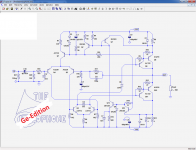
I see ASY73, Germanium NPN, TO5, 0.14W, 30V, 0.4A, 75C, 4MHz, 30pF, HFE20. . .All? No, something is missing.... but the gap is going to be filled very soon, thanks to the "Steamclophone"....... Details will follow
The steamclophone is born
http://www.diyaudio.com/forums/solid-state/269928-circlophone-germanium-edition.html#post4227144
http://www.diyaudio.com/forums/solid-state/269928-circlophone-germanium-edition.html#post4227144
Steamclophone
That's great!!!
Eagerly waiting...
The Circlophone has successfully been built in all shapes and flavors: N and P, BJT, darlington, MOS....
All?
No, something is missing.... but the gap is going to be filled very soon, thanks to the "Steamclophone"
Details will follow
That's great!!!
Eagerly waiting...
Rule N°1: never misunderestimate Eva, she is smarter than you, me, and a good part of the forum's members put together.
...
Who is Eva?
She is the lady having posted this project for example:Who is Eva?
http://www.diyaudio.com/forums/powe...rt-circuit-no-relays-no-aux-transformers.html
Unfortunately, she doesn't seem to be active anymore on DIYaudio. A pity, she showed a deep understanding of electronics, and came out with really bright and creative ideas, like the "Evaquad" (naming is mine).
I like this schematic, had a good experience with some similar topology, about very low THD, some warm class AB, and what i want to try is this schematic with the 2N3055 replaced, correctly polarised by P210 russian, or ASZ15, pnp Ge power transistors because in my youth I had a very positive experience about how the slower Ge power-ends sounded.
That is here----> http://www.diyaudio.com/forums/solid-state/269928-circlophone-germanium-edition.htmlI like this schematic, had a good experience with some similar topology, about very low THD, some warm class AB, and what i want to try is this schematic with the 2N3055 replaced, correctly polarised by P210 russian, or ASZ15, pnp Ge power transistors because in my youth I had a very positive experience about how the slower Ge power-ends sounded.
You won't find Class B on an amplifier tracks the bias always ahead--that is Class AA.
She is the lady having posted this project for example:
http://www.diyaudio.com/forums/powe...rt-circuit-no-relays-no-aux-transformers.html
Unfortunately, she doesn't seem to be active anymore on DIYaudio. A pity, she showed a deep understanding of electronics, and came out with really bright and creative ideas, like the "Evaquad" (naming is mine).
Eva is absolutely fantastic.
So is Susan Parker.
Those are awesome in absolutely every way possible.
Also, those spared no effort to make sure of it.
Therefore doubly awesome or triply awesome.
I could not do the maths for this!
The Circlophone has successfully been built in all shapes and flavors: N and P, BJT, darlington, MOS....
All?
No, something is missing.... but the gap is going to be filled very soon, thanks to the "Steamclophone"
Details will follow
A rather important - at least for my purposes - feature is missing, a symmetric input. My DIY preamp has symmetric XLR outputs only. For the active speaker with two circlophones i want eventually the advantages of symmetric signals .
What is the simplest way to upgrade the standard circlophone to XLR input? I made a test with an opamp OPA 627 and 2 voltage stabilisator ICs but got some hum which is not there without this pre-stage.
What is the simplest way to upgrade the standard circlophone to XLR input?
I asked similar question in earlier:
http://www.diyaudio.com/forums/solid-state/189599-my-little-cheap-circlophone-27.html#post2702281
Best solution is bridged configuration for balanced source in my opinion.
This following question was most likely been asked before....
for my active speaker project , 50 watts for the woofer/midrange is enough above 150 Hz, for the Dynaudio tweeter, according to amplitude/frequency statistics, 20 watts will do.
So question a.) is what is the lowest supply voltage for the circlophone without negatively affecting performance?
and b.) what is the simplest method to reduce the supply voltage accordingly ( and most important the idle dissipation as heatsink size is limited by speaker dimension) ?
Of course the voltage reduction should be near loss-less. Thus a dc/dc converter?
I think it can be done without inductors, capacitors only.
It can be made to work at very low voltages, the main drawback being the "normal" OP stage, wasting 1 or 2V on either side of the supply.This following question was most likely been asked before....
for my active speaker project , 50 watts for the woofer/midrange is enough above 150 Hz, for the Dynaudio tweeter, according to amplitude/frequency statistics, 20 watts will do.
So question a.) is what is the lowest supply voltage for the circlophone without negatively affecting performance?
Low voltage, efficient amplifiers normally use some common emitter variant to reduce the losses to Vce sat.
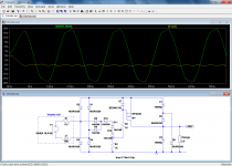
That said, the circlophone manages to be relatively efficient even at those low voltages.
Here is an example operating on 12V (tested in sim only):
http://www.diyaudio.com/forums/solid-state/189599-my-little-cheap-circlophone-130.html#post4163976
http://www.diyaudio.com/forums/solid-state/189599-my-little-cheap-circlophone-42.html#post2844622
The lowest voltage that has actually been tested is 20V (10+10V)IIRC
Yes, it can be done with capacitors only, but I am not sure it is the simplest solution: a single inductor synchronous buck converter requires less switching elements and is probably much more efficient.and b.) what is the simplest method to reduce the supply voltage accordingly ( and most important the idle dissipation as heatsink size is limited by speaker dimension) ?
Of course the voltage reduction should be near loss-less. Thus a dc/dc converter?
I think it can be done without inductors, capacitors only.
Anyway, I don't think I have a capacitive voltage divider in my files for such a power, but I think I have a voltage dividing rectifier (the reciprocal function of a voltage multiplier). Would that be suitable? If you start from a conventional 50 Hz AC PSU, it should be OK
OK, here is the power rectifier/divider 2). Not exactly simple, but it does the job.
It could probably be coupled/merged with a synchronous rectifier for improved efficiency, but that would require a significant design effort.
Maybe I will make an attempt when I feel like it.
2). Not exactly simple, but it does the job.It could probably be coupled/merged with a synchronous rectifier for improved efficiency, but that would require a significant design effort.
Maybe I will make an attempt when I feel like it.
Attachments
if the ratio of powers low/mid to hi is say 50/20 the ratio of voltages must be the square root of 2.5 . There are tons of dc dc step down converters even inexpensive with adjustable output - via pulse width - but i don't have any experience how these would do in audio amp applications. As far as i see it at first glance your voltage dividing rectifier can only produce half voltage, thus would yield a ratio of powers of 4. That could do perhaps.
If you chose an over-dimensioned type to take into account the peak supply current (instantaneous) plus some margin, and you add a sufficient bypass cap (eg. 4700µ) it should work well enoughif the ratio of powers low/mid to hi is say 50/20 the ratio of voltages must be the square root of 2.5 . There are tons of dc dc step down converters even inexpensive with adjustable output - via pulse width - but i don't have any experience how these would do in audio amp applications.
YesAs far as i see it at first glance your voltage dividing rectifier can only produce half voltage, thus would yield a ratio of powers of 4.
- Home
- Amplifiers
- Solid State
- ♫♪ My little cheap Circlophone© ♫♪