The fuse is possibly not a brilliant idea as there is no simple implementation of a "fuse blown" indicator. Further in that case the fb loop is open within the threshold voltage of the antiparallel diodes. So ok., good old relay.
Why not put a 220nF or so capacitor across the fuse? The sound will be so bad it'lls be obvious something is wrong. Then write something on the chassis to explain to check the fuse if it starts sounding bad.
That's brilliant, but I think you'd need a bigger cap if you want to hear some signal despite a fuse blown. A likely range is 2u~330u. That's very doable with a 2u~4u7 polyester cap.
Alternative: Automotive blade fuses aren't very inductive and could be used outside the feedback loop more easily.
Alternative: Automotive blade fuses aren't very inductive and could be used outside the feedback loop more easily.
Rod Elliot says fuses aren't really effective, and suggests a PTC thermistor instead:
Speaker Failure Analysis
Speaker Failure Analysis
It depends on what you are protecting against: If you're always on the edge, pushing as much power as possible through your speakers, using a fuse to protect them from your excessive optimism is going to work moderately well at best.
If you just want protection against a gross defect, like a blown OP transistor, or DC ingress in the amplification chain, then a correctly dimensionned fuse will be very effective.
By correctly dimensioned, I mean just above the maximum unclipped rms current for a music program, which is going to be much less than the rms current in sine regime, and much much less than the peak current the amp is capable of delivering under normal conditions.
In addition, the fuse should be of the fast variety. If you simply insert such a fuse into the output of an amplifier, it will severely distort the signal: for a 100W/8Ω amp, it would be something like 0.63A, but in the FB loop, it is transparent, and can offer a good protection at the same time.
Eliott's idea with PTC is to provide thermal-image protection, something that is widespread in the industry, for big motors, etc.
Nothing wrong with that, but the parameters of the image have to match closely those of the real thing, otherwise it is dangerously useless, or annoying.
I am not sure the PTC you are going to chose more or less randomly (regarding thermal inertia) is going to match your voice-coil accurately; I suspect that its mass being larger, and its materials being mostly different than metals, its thermal capacity will be larger. Since the power it dissipates will (hopefully) be smaller than what the coil does, it will heat more slowly, unless you chose a really small one, therefore the protection won't be that effective, and PTC's on the edge are no more linear than fuses.
That said, fuses also have some in-built thermal imaging capacity: if you look at the characteristic curves of fuses, fusing time vs overcurrent, you'll see that for its nominal current, even a so-called "fast fuse" takes forever to open the circuit; yet the thermal inertia of a fuse is much smaller than that of a PTC.
Anyway an indicator is more professional than a gues for ex. by low volume and much distortion. The case could be the amp or the speaker.
I had very little time and have just finished one circlo for parallel operation with existing amp. For that purpose the PCB must be "pin compatible" and dimension compatible and hence is not of general interest. The amp has offset adjust as proposed by Elvee, and i added a 25 k pot 10 turn in series with R21 ( 33 k) to find out the influence of quiescent current between about 140 mA and 200 mA. The OS has BD317. A listening comparison for sonic qualities was performed as such both inputs are fed from Opamp ( TL072) outputs which has gain set to 5, has a pot at inputs which are both connected to the same output of an RIAA amp. The pots are adjusted ( by means of a test LP) to give the same output level at both amps. A simple switch connects one speaker box to either one or the other amp output
The test signal LP did not unveil audible difference.
With some more LPs, with real music, I got one by one the impression the Circlo sounds somehow softer and more transparent, it mastered abrupt changes in volume of the recordings audibly better than the original amp which is a full symmetric CFA with clever lead lag compensation and SOAR protection. ( And therefore needs 6 supply voltages).
I think the differences may be due to the harmonics spectrum ( switching vs not switching, further full symmetry cancels even harmonics but not odd harmonics as well) and the thermal stability vs thermal lag. As the symmetric PSU is rather soft, the supply voltage is between +- 39 Volts idle and +- 31 volts at max power. Insofar i could not detect influence of quiescent current set by R21 and the 25 k pot in series. However the subjective transparency of sound reproduction appears to increase with idling current .
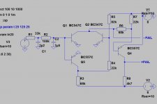
More or less true at first sight, but less so on closer examination: here the VAS is a diff-amp, and except for inaccuracies introduced by the crude tail current definition, and base currents variations caused by Vce-induced Hfe variations, any Ic variation on one side is mechanically reflected on the other.The second harmonic of the VAS is not canceled in this topology, because one side of the VAS experiences the full output voltage swing and the other does not.
This mostly cancels even order harmonics, and this is confirmed by the harmonic profile: the 2nd is present, but clearly below the third.
Besides that harmonics measurement with soundcard and software may not be very accurate, what i found for the circlo is that the second harmonics is significantly higher than third, there are 20 dB between 2nd and 3rd. This is btw the preferred profile. If i get some time i might try to measure the harmonics inclusive of speaker. That is even more inaccurate but after all is what eventually matters
Trivial solution to an indicating fuse.
Use a Telecommunications GMT fuse and holder to derive fuse blown signal.
Audio is just a Minor subset of Electronics Technology.
Hum a relay is cheaper. Of course, a dc detector is anyway required.
Re fuse...Circlophone is much cheaper than a woofer or midrange or broadband speaker thus the objective is to protect the speaker. As any malfunction/ defect of the circlo will either show up as dc at output or oscillation, it is advisable to provide at least a dc detector. An oscillation detector is not so easy, a simple approach is a differential amp that compares input and ( attenuated by circlo's gain) output. I am not sure whether a fast fuse blows fast enough to save a tweeter from a sudden + Vs at output. For Vs= 35 volts and R voice coil= 5 ohms the dissipation is 245 watts. Thus a reaction time to disconnection should be around 1 msec.
For a tweeter, it is possible to insert a capacitor large enough not to interfere with the filtering, but small enough to save the coil should a problem happen.
That said, I don't think 1ms would be enough to fry the coil: I didn't make a numerical estimation based on thermal capacity of copper, etc, but my physical sense of reality tells me that for a large enough ΔT°, you would need more than 1ms.
Oscillation remains a risk even with the cap, but the likelihood of such a destructive event seems limited: I and other people have observed oscillations from time to time on some units, due to inadequacies between transistors and compensation or problems like capacitors missing or the wrong values, but the oscillations were always low in level (sometimes barely detectable), and high in frequency, >1MHz.
This is normally harmless to tweeters.
Of course, there might be other fault conditions like dried E-caps that could possibly cause high voltage, low frequency (tens of KHz) oscillations, but it has never been observed so far.
I do a weird thing for that, always.For a tweeter, it is possible to insert a capacitor large enough not to interfere with the filtering, but small enough to save the coil should a problem happen.. . .
I put a series cap on the tweeter pole opposite the crossover.
That tweeter never breaks--no exceptions.
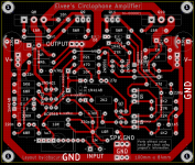
Hi. I'm building the Circlophone and need some help. I finished one channel prototype. Board layout will be attached to this post. It sounded but when no input connect and I listen very close to the speaker, I hear some noise out of it. Since it is my first power amply build, I need your help about it.
- My build is default Circlophone. But I added 10 Ohms ground breaker resistor.
- Shorted input won't make the noise goes away.
- PSU is 4x10000uf 63V.
- Here is the url of the recorded music which I used my phone to record when it was ~ 2-3 cm close to the speaker. No input connected.
https://dl.dropboxusercontent.com/u/2696654/Voice%20010.m4a
Attachments
From what I can gather, this hum sounds like ripple, but not base ripple: more the harmonics than the 100 or 120Hz (an oscillogram would be more helpful than the sound).but when no input connect and I listen very close to the speaker, I hear some noise out of it.
Your layout looks a bit strange, but I don't see where it could pose problems, except perhaps in the tracks leading to the local 220µ bypass caps.
You could try to remove them, or reduce them to something symbolic, like 470nF, to see if it changes something.
In principle, with the main filter caps you use, local problems should be very attenuated, but their large value could cause other problems: are you testing your amp in its final configuration, or do you have the boards and supply spread on a table, with flying leads?
The inductively coupled charging spikes of the filter caps could very well sound like that.
Try changing the position of the power wiring, in particular the secondary of the transformer, the output of the rectifier bridge. Be also careful about the ground lead of the supply, how is it connected wrt. to the filter caps and center tap.
Anyway, try as many things as you can think of: reverse the mains supply plug, short the ground-breaking resistor, try feeding it with a lab supply, try various shields at various locations: magnetic and electrostatic.
Any additional information this produces, even negatives, will help in pinpointing the origin of this hum
From what I can gather, this hum sounds like ripple, but not base ripple: more the harmonics than the 100 or 120Hz (an oscillogram would be more helpful than the sound).
Your layout looks a bit strange, but I don't see where it could pose problems, except perhaps in the tracks leading to the local 220µ bypass caps.
You could try to remove them, or reduce them to something symbolic, like 470nF, to see if it changes something.
In principle, with the main filter caps you use, local problems should be very attenuated, but their large value could cause other problems: are you testing your amp in its final configuration, or do you have the boards and supply spread on a table, with flying leads?
The inductively coupled charging spikes of the filter caps could very well sound like that.
Try changing the position of the power wiring, in particular the secondary of the transformer, the output of the rectifier bridge. Be also careful about the ground lead of the supply, how is it connected wrt. to the filter caps and center tap.
Anyway, try as many things as you can think of: reverse the mains supply plug, short the ground-breaking resistor, try feeding it with a lab supply, try various shields at various locations: magnetic and electrostatic.
Any additional information this produces, even negatives, will help in pinpointing the origin of this hum
Thanks for the help. This noise is very low, I can only hear it when my ear are 1cm close to the speaker. When I open the record file with arta, it is max -64db and seem base at -84db. There are some clock tickling and some one cough in it so it is not so correct.
The amp only at test step. Both AMP and PSU had their own PCBs, place in a test place.
So I need to try these:
- reverse the mains supply plug
- short the ground-breaking resistor
- try various shields at various locations
- try to use another cable to speaker.
- I moved wires around and decrease the noise a bit.
- I shorted the ground-breaking resistor - same noise.
- I shorted input to ground -> no noise any more
As I read, if I shorted input and not hear any noise then it come from outside of the amp? Is my prototype seem ok now?
- I shorted the ground-breaking resistor - same noise.
- I shorted input to ground -> no noise any more
As I read, if I shorted input and not hear any noise then it come from outside of the amp? Is my prototype seem ok now?
Yes, it is probaly electrostatically coupled hum from the input wiring.As I read, if I shorted input and not hear any noise then it come from outside of the amp? Is my prototype seem ok now?
Did you use shielded cable? Is the metal frame of your volume pot grounded.
How is you input connector grounded, chassis....?
Is the amp board itself close to the transformer, or power or AC wiring?
- Home
- Amplifiers
- Solid State
- ♫♪ My little cheap Circlophone© ♫♪