Fuses are ugly little goblins having significant resistance and thermal distortion.
When they are included in the FB loop, all of this is mostly polished off. Here is a technique to do it properly:
http://www.diyaudio.com/forums/solid-state/189599-my-little-cheap-circlophone-50.html#post2864168
When they are included in the FB loop, all of this is mostly polished off. Here is a technique to do it properly:
http://www.diyaudio.com/forums/solid-state/189599-my-little-cheap-circlophone-50.html#post2864168
Need to change PCB design anyway for clipping detector and overload indicator. These are standard for active speakers besides more sophisticated amplitude and frequency dependent limiters.
Will you be publishing the final circuit adopted by you with all modifications and details of PCB?
Possibly yes. However the issues and items which are specific for active speakers is another topicWill you be publishing the final circuit adopted by you with all modifications and details of PCB?
Have you looked at the solutions provided in the thread?Need to change PCB design anyway for clipping detector and overload indicator.
http://www.diyaudio.com/forums/solid-state/189599-my-little-cheap-circlophone-45.html#post2853257
There is also a soft clipping variant asked for by Daniel, somewhere
Have you looked at the solutions provided in the thread?
http://www.diyaudio.com/forums/solid-state/189599-my-little-cheap-circlophone-45.html#post2853257
There is also a soft clipping variant asked for by Daniel, somewhere
Yes these will be implemented offset setting overload indicator clipping indicator and or soft clipper as you proposed in this thread, and speaker protector with fuse in FB loop. An additional Dc detector might be necessary as malfunction indicator, and an overheat detector as well.
The rest is speaker- specific , i.e. to prevent cone excursions above the respective x max of the woofer improves the bass response far more than any thd mania. Negative output resistance ( or better complex output impedance with a negative real part) is also speaker/enclosure specific.
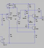
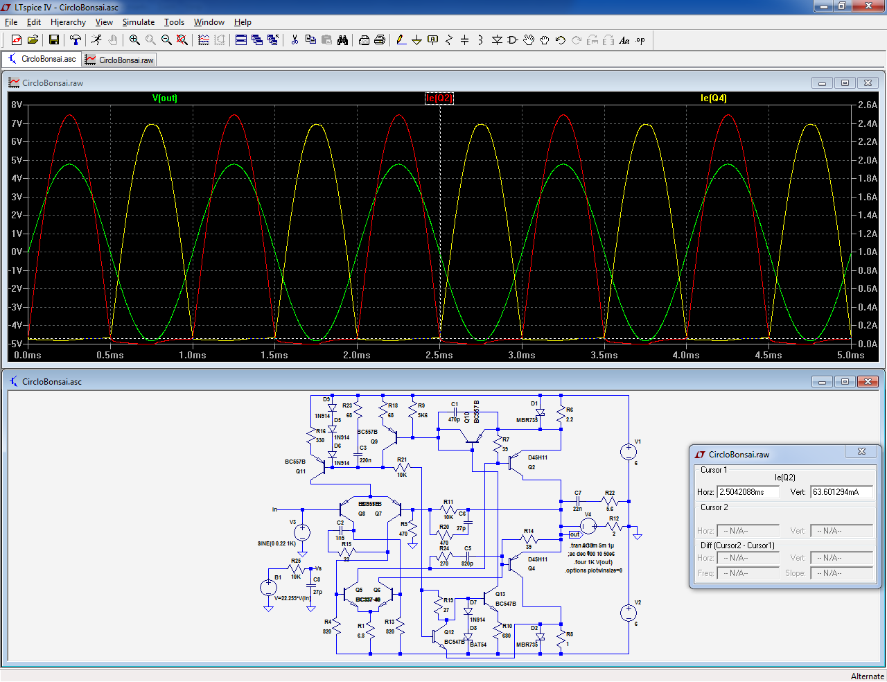
Just wanted to say thank you for this. I will attempt a build in 2015.Here is an attempt at a midget Circlophone: CircloBonsaï.
6W to 2R is. . . 1.5W to 8R?Here is an attempt at a midget Circlophone: CircloBonsaï. The modifications consist mainly of simplifications: singles as OP, no zener, and a few resistor values adapted. The Iq has been reduced to 65mA
With 12V total supply (+/-6V), it delivers 10Vpp into 2Ω before clipping, that is 6W average power. 2V total waste is not bad for a general purpose amplifier, but cannot compare with specialized amplifiers for car radio and other low voltage applications having common emitter output.. . .
schema
Um, twice that much is half enough.
Problem is that I'm fresh out of 5cm 2 ohm speakers and don't happen to need a 3/4 watt headphone amp.
") Its kind of in "no man's land" for power range, where a lot of transistors did not much. So, what does it look like at about 7W to 8R? That's just about the minimum for a biggie size table radio and/or computer desktop speakers that doesn't clip a lot.
Its kind of in "no man's land" for power range, where a lot of transistors did not much. So, what does it look like at about 7W to 8R? That's just about the minimum for a biggie size table radio and/or computer desktop speakers that doesn't clip a lot. P.S.
Cheapest possible power supply for audio amplifier is 15v power pack from ebay for about $8, although 19v and 24v are available for not much. Single rail, of course.
P.P.S.
MBR diodes standing by. . . although, specifically, MBR1645 has several more entertaining uses at the amplifier board, such as splitting a stereo supply to, effectively a dual mono supply (this is really very much more entertaining than one might assume by reading). Is that feature inherent with a circlophone? Sounds very awesome with a normal amp or even a chip amp, so I'm curious, very curious, if that feature is an integral part of Circlophone??? It levels the tone fairly well (this is a fantastic feature). Otherwise, I don't know what it does.
According to the datasheet, the DH44 output has half the capacitance of the DH45, and that will generally mean that the DH44 has half the device noise (parasitic capacitance makes discharge noise, so Half as much is generally a good idea). The simulator would probably show them as unrelated devices. To me, the difference means that the DH44's lower capacitance could be used for either higher speed or lower noise or lower bias. I'm not sure which of those three features is more interesting, but it probably would be good to use at least one of the provisions. In this case, the "sex change" looks like a good idea, because using the better output device. Truly, it probably isn't a practical difference to the audio band, but at least the sim jockeys will be much more entertained with the DH44.The circuit could also undergo a complete sex-change operation, or operate in a single supply config as shown above: this would give a slight advantage for output power, because the positive side has a little more headroom, and with a proper bias, 10.5~11Vpp output would be possible.
Also, the charts say to me that the DH44 and/or DH45 will lay over at about 11 watts when driving a speaker with the circlo, exposing the next smaller devices to more load. Well, that's okay for an amp proposed at less than 11 watts, isn't it?
P.S.
And then there's a slightly evil thought--when it comes to simplicity with output devices, nothing beats a unit darlington. You know, just in case we need both simplicity and more than 11 watts.
Last edited:
Yes, approximately.6W to 2R is. . . 1.5W to 8R?
Like most amplifiers, the Circlophone is not married to a specific voltage: the low voltage example I have provided could also work at 6V or 24V, but you have to take one or two things into account:Its kind of in "no man's land" for power range, where a lot of transistors did not much. So, what does it look like at about 7W to 8R? That's just about the minimum for a biggie size table radio and/or computer desktop speakers that doesn't clip a lot.
Because the OP transistors are now single, the drive current has been increased to be able to drive 2Ω comfortably. This means that the dissipation in Q5/Q6 is tripled, which is OK for 12V but for higher voltages, a type accepting a heatsink would be required.
If you don't want to drive 2Ω, the current can be reduced, but at higher voltage, the load will take more current, even if it is 8Ω.
You need to decide a supply voltage, an output power, and see if everything adds up.
With superbeta's as OP, things would be easier. The D44/45 have a decent Hfe, but they do not qualify as superbeta.
That would be about 2W/8ΩP.S.
Cheapest possible power supply for audio amplifier is 15v power pack from ebay for about $8,
The schottky's only role is dissipation reduction in the sensing shunts.... not very entertainingMBR diodes standing by. . . although, specifically, MBR1645 has several more entertaining uses at the amplifier board, such as splitting a stereo supply to, effectively a dual mono supply (this is really very much more entertaining than one might assume by reading). Is that feature inherent with a circlophone? Sounds very awesome with a normal amp or even a chip amp, so I'm curious, very curious, if that feature is an integral part of Circlophone??? It levels the tone fairly well (this is a fantastic feature). Otherwise, I don't know what it does.
In general, N devices are faster and have a lower capacitance compared to PAccording to the datasheet, the DH44 output has half the capacitance of the DH45, and that will generally mean that the DH44 has half the device noise (parasitic capacitance makes discharge noise, so Half as much is generally a good idea). The simulator would probably show them as unrelated devices. To me, the difference means that the DH44's lower capacitance could be used for either higher speed or lower noise or lower bias. I'm not sure which of those three features is more interesting, but it probably would be good to use at least one of the provisions. In this case, the "sex change" looks like a good idea, because using the better output device. Truly, it probably isn't a practical difference to the audio band, but at least the sim jockeys will be much more entertained with the DH44.
Also, the charts say to me that the DH44 and/or DH45 will lay over at about 11 watts when driving a speaker with the circlo, exposing the next smaller devices to more load. Well, that's okay for an amp proposed at less than 11 watts, isn't it?
Terranigma has done itP.S.
And then there's a slightly evil thought--when it comes to simplicity with output devices, nothing beats a unit darlington. You know, just in case we need both simplicity and more than 11 watts.
As the said speaker boxes intended to be activated with circlophones suffers from some
acoustical problems - resonances of the enclosure and not air tight - i will now start testing circlophones in a triamp. That one has at least an excellently wired PSu - mains filters, 2 transformers, large ground bar and many more, so i have just to replace the existing amp boards with circlo boards. The output devices are old BD317, which are a bit slower than the later versions of 2N3055 with fT min 1 MHz. The older 2N3055 ( hometaxial, i.e. single diffused ) technologies have max 0.5 MHz fT, the newer (epi base)
reach ft 3Mhz. Soon i might know more.
The predriver is what is there . It features an output impedance of about 15 Ohms . Is that still ok. for circlophone? And second question compensation scheme. It appears that the BD137 is somewhat slower than 2N6259 and also slower than "contemporary" 2N3055.
There is no Spice model for it. I want to run a subjective comparison between the circlo and the built in amp driving 2 way shelf speakers, and subwoofers as well. I need some extended practice with the circlo before I run the risk of killing the quite expensive broadband and woofer of the intended active speaker.
There is no Spice model for it. I want to run a subjective comparison between the circlo and the built in amp driving 2 way shelf speakers, and subwoofers as well. I need some extended practice with the circlo before I run the risk of killing the quite expensive broadband and woofer of the intended active speaker.
typo BD317T It appears that the BD137 is somewhat slower
The BD317 (made by Tesla) is among the types I have actually tested:
http://www.diyaudio.com/forums/solid-state/189599-my-little-cheap-circlophone-2.html#post2585337.
Is your predriver going to be placed in front of the Circlophone?
If that is the case, there is no problem at all: 15 ohm is much lower than the 2~3 KΩ it tolerates without degradation
http://www.diyaudio.com/forums/solid-state/189599-my-little-cheap-circlophone-2.html#post2585337.
Is your predriver going to be placed in front of the Circlophone?
If that is the case, there is no problem at all: 15 ohm is much lower than the 2~3 KΩ it tolerates without degradation
That all looks like good news.
A buffer or preamplifier at the input is beneficial (if there's No volume pot in-between the amp and pre).
The BD317 and modern similar devices like MJ802, MJ15003, are ideal for use in non-switching amplifiers like CircloPhone (non-switching application is when the high capacitance device isn't discharged so there's no crispy noise), and the switching speed is not as important for audio.
For phase linearity (in non-switching or dynamic bias or very high bias amplifiers), you'll want an output device rated 0.5MHz higher than the amplifier's output signal. So, for the audio band, that range is 0.53MHz (min) to 11MHz (max). The MJ21194, NJ21196 is in the middle of that range, and with very high linearity (quality). However, that sets the bar really high at 3.5MHz Phase Linear, and actually achieving that needs extra parts, a lot of adjustment, and a very big workout that we'd probably like to avoid. This matter is much easier with the MJ15003, which is half as fast so the amplifier need only get up to 1.5MHz to achieve pure phase linearity. Meanwhile, down at 1MHz, the BD317 could provide a far easier time with the phase linearity, since the amplifier need only run at 500KHz, and this probably won't require much adjustment, if any. That is very, very good!!
So, although the sweet spot range for fastest phase linear performance is a bit high at 4~6MHz (the amp goes 3.5~5.5MHz) and could make an awesome radio transmitter; However, for amplifying the audio band, there's a more important consideration of suitable and doable (without a huge amount of compensation adjustments, parts and labor), so the range of doable has a lower frequency of 1MHz~3MHz, so long as the output is sturdy and highly linear. Well, that means for non-switching applications, you're looking to use BD317, MJ802, MJ15003, BD294C (and sturdy fets), on purpose, so as to more easily achieve a far higher quality practical performance in the audio band.
I'm just trying to say that shopping for the fastest possible outputs is not a good practice if the application is non-switching. For amplifiers that switch the outputs, high speed outputs have one thing in common, which is very low capacitance, and rather than ludicrous speed useless to the audio band, it is the low capacitance that is useful for switching amplifiers and low bias amplifiers. The latter is not a circlophone. What we actually should be shopping for is highest linearity, and that shopping is much easier because it is a very short list. It is similar to shopping for outputs suited to a normal Class A amplifier.
For "workbench speaker" and test situations and for LF frequency control (define the audio band?):
This speaker filter is made bipolar for amplifiers that don't require output caps, such as split rail and BTL, in which case, the series filter shown should go at the speaker negative. That entire unit can be bypassed by something much like 4.7uF Nichicon ES (or a hv polyester) for having the tweeter signal go though a little cap very cleanly.
The item shown above will protect the speaker from DC output accidents.
However, it is traditionally (?) used with subwoofers (and woofers) to achieve greater bass extension in sealed box cabinets (or more rarely, it can be used for altering port tuning to reduce booming). A very similar approach of favorable LF control is done with portables, generally by carefully sizing the output cap to match the speaker LF capacity so that inaudible sub-bass pitches don't waste battery power.
For all of the LF control cases, the capacitance value is re-sized to suit one particular speaker ideally.
I did not and would not consider spending a similar amount on a relay system, except for cases where this rather large cap unit couldn't fit an enclosure.
Unexpected usage: Intended for DC blocker, but re-deployed for far higher quality bass.
Clipping control:
A device similar to this can be used to clip the small signal before the outputs could clip, and a small signal clip recovers faster with less noise.
Unmentioned in the notes, that extra 470R also controls some amount of compensation and imaging. It may be fun to try this circuit made with entirely multi-turn trimmers.
Unexplained: The imaging difference exhibits standard behavior for the gain compensation setting of an amplifier, so if the 470R is reduced, the imaging performance increases DRAMATICALLY at the cost of a slightly less favorable tone.
Balance as needed by adjusting that resistor value (the newly added 470R). I had actually used 1n400x instead of the 1n914, and it is notable the the capacitance is different--the 1n400x is 15pf (in the datasheet), I've got them paralleled, so you're also looking at 30pf. Anyway, I think this circuit is sensitive to capacitance.
Unfortunately, I had moved on to other projects before trying: Omit the 1n5819, replace the new 470R with a 500R (or 1k) cermet multi-turn trimmer configured as a variable resistor, replace the pair of 1n914 with a single 30pF cap, then turn the trimmer to find out if the variable imaging control still functions without any diodes.
Unexpected usage: Intended to block clipping but re-deployed for a form of compensation to affect imaging performance positively. The intended performance also worked because it prevented me from overrunning the output device linearity and therefore at full blast there was no awkward shift in either performance or tone.
X-Max control:
This little bit of crudeness is a thump blocker, simply 2 inversely series zeners added to the input load, adds a little bit of capacitance (half as much as one zener) and shortens power-on thumps from attached single rail devices, such as your computer. Theoretically, some series resistance, such as 330R series to the input (use your source's power voltage, half of your Zener's amperage rating and punch those into an LED calculator to determine the smallest usable resistor value), is required so as to preserve the zeners lifespan, but mine have never quit as shown, probably because I have a volume pot that isn't all the way up. That thump blocker application is normally shown with the addition of an inversely series pair of low capacitance diodes, set series to the zeners to reduce the overall capacitance of the diode string; however, I measured a whole box of zeners and determined that half as much capacitance of even the highest one was barely enough to be useful blocking some RF and surely not harmful to the audio band. Shortly after publishing that, I discovered that my zeners are actually the extra cheap LED bypass version, which are an imprecise slightly less than 3.7v, for if a lighting grade 3v per unit led string loses a bulb, the rest don't quit. So, the 5v1 shown is a higher value than I actually used.
Man that schema needs remade! However, the concept is really simple. Reducing the computer's 12v spike is what the accessory circuit is made for--I run the suspend mode power saving with my computer, so without this accessory, waking up the computer resulted in an almost plaster cracking explosion. It wasn't boring, but doing without that fright was alright.
Unexplained: When the circlophone is not exposed to any big input spikes, the behavior is generally higher resolution for a longer duration, less errata, and so, the simple addition was more useful than intended.
Unexpected usage: Intended to block power-on thumps but re-deployed to reduce amplifier erratas. Actually, my build of circlophone had really really a LOT of crazy behaviors, but this simplicity stopped/calmed/normalized most of it. So, I think that circlo does not like input spikes.
Footnote:
If the capacitance of any part mentioned in this post is changed, the function for audio will also be changed. That may be either great fun or slightly time consuming, probably both.
A buffer or preamplifier at the input is beneficial (if there's No volume pot in-between the amp and pre).
The BD317 and modern similar devices like MJ802, MJ15003, are ideal for use in non-switching amplifiers like CircloPhone (non-switching application is when the high capacitance device isn't discharged so there's no crispy noise), and the switching speed is not as important for audio.
For phase linearity (in non-switching or dynamic bias or very high bias amplifiers), you'll want an output device rated 0.5MHz higher than the amplifier's output signal. So, for the audio band, that range is 0.53MHz (min) to 11MHz (max). The MJ21194, NJ21196 is in the middle of that range, and with very high linearity (quality). However, that sets the bar really high at 3.5MHz Phase Linear, and actually achieving that needs extra parts, a lot of adjustment, and a very big workout that we'd probably like to avoid. This matter is much easier with the MJ15003, which is half as fast so the amplifier need only get up to 1.5MHz to achieve pure phase linearity. Meanwhile, down at 1MHz, the BD317 could provide a far easier time with the phase linearity, since the amplifier need only run at 500KHz, and this probably won't require much adjustment, if any. That is very, very good!!
So, although the sweet spot range for fastest phase linear performance is a bit high at 4~6MHz (the amp goes 3.5~5.5MHz) and could make an awesome radio transmitter; However, for amplifying the audio band, there's a more important consideration of suitable and doable (without a huge amount of compensation adjustments, parts and labor), so the range of doable has a lower frequency of 1MHz~3MHz, so long as the output is sturdy and highly linear. Well, that means for non-switching applications, you're looking to use BD317, MJ802, MJ15003, BD294C (and sturdy fets), on purpose, so as to more easily achieve a far higher quality practical performance in the audio band.
I'm just trying to say that shopping for the fastest possible outputs is not a good practice if the application is non-switching. For amplifiers that switch the outputs, high speed outputs have one thing in common, which is very low capacitance, and rather than ludicrous speed useless to the audio band, it is the low capacitance that is useful for switching amplifiers and low bias amplifiers. The latter is not a circlophone. What we actually should be shopping for is highest linearity, and that shopping is much easier because it is a very short list. It is similar to shopping for outputs suited to a normal Class A amplifier.
DC controlhahfran said:I need some extended practice with the circlo before I run the risk of killing the quite expensive broadband and woofer of the intended active speaker.
For "workbench speaker" and test situations and for LF frequency control (define the audio band?):
This speaker filter is made bipolar for amplifiers that don't require output caps, such as split rail and BTL, in which case, the series filter shown should go at the speaker negative. That entire unit can be bypassed by something much like 4.7uF Nichicon ES (or a hv polyester) for having the tweeter signal go though a little cap very cleanly.
The item shown above will protect the speaker from DC output accidents.
However, it is traditionally (?) used with subwoofers (and woofers) to achieve greater bass extension in sealed box cabinets (or more rarely, it can be used for altering port tuning to reduce booming). A very similar approach of favorable LF control is done with portables, generally by carefully sizing the output cap to match the speaker LF capacity so that inaudible sub-bass pitches don't waste battery power.
For all of the LF control cases, the capacitance value is re-sized to suit one particular speaker ideally.
I did not and would not consider spending a similar amount on a relay system, except for cases where this rather large cap unit couldn't fit an enclosure.
Unexpected usage: Intended for DC blocker, but re-deployed for far higher quality bass.
Clipping control:
A device similar to this can be used to clip the small signal before the outputs could clip, and a small signal clip recovers faster with less noise.
Unmentioned in the notes, that extra 470R also controls some amount of compensation and imaging. It may be fun to try this circuit made with entirely multi-turn trimmers.
Unexplained: The imaging difference exhibits standard behavior for the gain compensation setting of an amplifier, so if the 470R is reduced, the imaging performance increases DRAMATICALLY at the cost of a slightly less favorable tone.
Balance as needed by adjusting that resistor value (the newly added 470R). I had actually used 1n400x instead of the 1n914, and it is notable the the capacitance is different--the 1n400x is 15pf (in the datasheet), I've got them paralleled, so you're also looking at 30pf. Anyway, I think this circuit is sensitive to capacitance.
Unfortunately, I had moved on to other projects before trying: Omit the 1n5819, replace the new 470R with a 500R (or 1k) cermet multi-turn trimmer configured as a variable resistor, replace the pair of 1n914 with a single 30pF cap, then turn the trimmer to find out if the variable imaging control still functions without any diodes.
Unexpected usage: Intended to block clipping but re-deployed for a form of compensation to affect imaging performance positively. The intended performance also worked because it prevented me from overrunning the output device linearity and therefore at full blast there was no awkward shift in either performance or tone.
X-Max control:
This little bit of crudeness is a thump blocker, simply 2 inversely series zeners added to the input load, adds a little bit of capacitance (half as much as one zener) and shortens power-on thumps from attached single rail devices, such as your computer. Theoretically, some series resistance, such as 330R series to the input (use your source's power voltage, half of your Zener's amperage rating and punch those into an LED calculator to determine the smallest usable resistor value), is required so as to preserve the zeners lifespan, but mine have never quit as shown, probably because I have a volume pot that isn't all the way up. That thump blocker application is normally shown with the addition of an inversely series pair of low capacitance diodes, set series to the zeners to reduce the overall capacitance of the diode string; however, I measured a whole box of zeners and determined that half as much capacitance of even the highest one was barely enough to be useful blocking some RF and surely not harmful to the audio band. Shortly after publishing that, I discovered that my zeners are actually the extra cheap LED bypass version, which are an imprecise slightly less than 3.7v, for if a lighting grade 3v per unit led string loses a bulb, the rest don't quit. So, the 5v1 shown is a higher value than I actually used.
Man that schema needs remade! However, the concept is really simple. Reducing the computer's 12v spike is what the accessory circuit is made for--I run the suspend mode power saving with my computer, so without this accessory, waking up the computer resulted in an almost plaster cracking explosion. It wasn't boring, but doing without that fright was alright.
Unexplained: When the circlophone is not exposed to any big input spikes, the behavior is generally higher resolution for a longer duration, less errata, and so, the simple addition was more useful than intended.
Unexpected usage: Intended to block power-on thumps but re-deployed to reduce amplifier erratas. Actually, my build of circlophone had really really a LOT of crazy behaviors, but this simplicity stopped/calmed/normalized most of it. So, I think that circlo does not like input spikes.
Footnote:
If the capacitance of any part mentioned in this post is changed, the function for audio will also be changed. That may be either great fun or slightly time consuming, probably both.
Last edited:
- Home
- Amplifiers
- Solid State
- ♫♪ My little cheap Circlophone© ♫♪