You need to search alternative titles like "Schottky diodes":
Diodes | Transfer Multisort Elektronik - Electronic components
Diodes | Transfer Multisort Elektronik - Electronic components
You need to search alternative titles like "Schottky diodes":
Okey, but on schematics, they are barrier type ?....
I got lots of output transistors to choose from, will try all of them there. Most compact sized will be chosen.
Renu
There are preferable ouput transitors on:
http://www.diyaudio.com/forums/solid-state/209907-building-elvees-circlophone-documentation-parts-accessories-beginner-friendly.html
May be you can check it out. I used MJL21194 and found it is fine to me.
http://www.diyaudio.com/forums/solid-state/209907-building-elvees-circlophone-documentation-parts-accessories-beginner-friendly.html
May be you can check it out. I used MJL21194 and found it is fine to me.
Schottky diodes are often referred to as "Schottky barrier diodes" They are synonymous terms. Actually, "barrier diode", "Schottky diode" and "Schottky barrier diode" can all mean the same thing. If you read the list I linked to with your supplier, you will find the BAT85 and BAT86 types on that page, in newer versions, and they are quite cheap. You will also find near equivalents for MBR735 at your supplier too:Okey, but on schematics, they are barrier type ?....
Transfer Multisort Elektronik - On-line Catalogue | 145 000 products offered.
Okey, but on schematics, they are barrier type ?....
Renu
If you can't find schottky diode, use ultrafast diode like UF4007, I have tried them...works fine.
Regards!
Regulated supplies are a luxury which the Circlophone can do without.
But it will work, of course.
This design has built-in component tolerance, and will happily accept almost anything you throw at it.
So far, the following types have been actually tested:
-Various brands of 2N3055's
-2N3772 Moto
-2N6259 STC
-MJ15024 Moto
-BDY58 ST
-BDX95 Philips
-BD183 Philips
-BD317 Tesla
-2SD424 EIC
-2SD555 NEC
.... and I am probably forgetting one or two more.
For Q5 and Q6, I have tried 2N3019, 2N2219, 2N1893, and I just checked with 2N5551, it also works, but I'm afraid they are a bit borderline: at 25V supply, the dissipation will be close to the 350mW abs. max. Pd.
The circuit is so tolerant, it will even work with fake or mismatched transistors, or even a different output configuration.
This is illustrated in the following pics:
The first shows what happens when everything that should be matched has been deliberately sabotaged: it still work perfectly.
The second has a darlington substituted for the CFP: the distorsion is bit up, but it remains pretty good.
There are some things to keep in mind, though:
The compensations have been optimized for 2N3055's, and if you use very different transistors, there might be some slight differences in the dynamic behaviour: with 2N3772 or 2N6259's, the slew rate is somewhat decreased.
Also, if you use fast (Ft>5MHz) transistors, the capacitor C11 shown as optional on the schematic becomes mandatory to remove local instabilities, and the circuit becomes more sensitive to the lengths of cable to the transistors.
Your 2SD1718 falls into that category, with an Ft=20MHz. It is pretty similar to the BDY58, which has been tested and works fine with C11 (without C11, there are low level VHF oscillations).
Also, a general remark, the value of C12 at 820pF is probably an overkill, and 180pF should normally be enough in practically all circumstances.
Finally, Q5 and Q6 should have a low enough collector capacitance, less than 15pF.
Most of the TO5/TO39's are suitable, including for the dissipation.
Hey Elvee I've been following this thread for a while now but still havent found an answer so i figured it's best to ask you the designer these questions. First off i would like to thank you for this elegant design you made and share with us. I want to build your amp straight out of metal can transistors for the classic look. i just happen to have the 2N3019 and a bunch of TO-18 transistors which leads my question to you: can i susbsiuite the 2N2222A and 2N2097A's for the BC556/BC546's and 2N3019/2n3044 or 2N2219/2N2905A for the BD139/BD140 pair? do you think it will work? I've seen you substituted 2N2222 for 2 transistors in one of your simulation diagrams but kept the other BC transistors so i wasn't sure. Also do you think the 2N3054 would be a suitable substitute for the 2N3055 finals for lower power&voltage operation? thank you so much Elvee and i really really like your design!
Thanks for your kind comments. I wouldn't call this design elegant though: it is effective and pigheaded, yet graceful and forgiving. I would have preferred to include elegance as well, and I made successful attempts in that direction, but the end result, although formally better looking, was not up to my expectations: I wanted a real good amp, not just an impressive spec sheet: something real, good, robust and pleasant, even with crap components.Hey Elvee I've been following this thread for a while now but still havent found an answer so i figured it's best to ask you the designer these questions. First off i would like to thank you for this elegant design you made and share with us.
That goal has been achieved, but honestly, the resulting circuit looks like a mess. Its essential redeeming feature is that it actually works extremely well....
Sometimes, you have to pinch your nose and accept that what you have in front of you is best possible tradeoff.
You have to mind the Vce's: the 2N tend to have a lower Vceo than BC546/556, and if you operate your amp at "high voltages", this could be a problemI want to build your amp straight out of metal can transistors for the classic look. i just happen to have the 2N3019 and a bunch of TO-18 transistors which leads my question to you: can i susbsiuite the 2N2222A and 2N2097A's for the BC556/BC546's and 2N3019/2n3044 or 2N2219/2N2905A for the BD139/BD140 pair?
Same remark, and in addition, the dissipation will be non-negligible: a few 100's mW or even watts depending on the supply voltage. With sufficient heatsinking, it can be done (I've done it) but certainly not with the bare transistors.do you think it will work? or 2N2219/2N2905A for the BD139/BD140 pair? do you think it will work?
.I've seen you substituted 2N2222 for 2 transistors in one of your simulation diagrams but kept the other BC transistors so i wasn't sure
The subs I made in the sims should not serve as examples: the models generally have a decorative, non-operational breakdown rating . I use models conveniently to illustrate one point or another, but for real circuits, you have to care about the ussual realities.
The 3054 is an oldish, medium power transistor, even more outdated than the 3055. Not exactly a good choice for a modern build (the 3055 is different: it has become a true commodity).Also do you think the 2N3054 would be a suitable substitute for the 2N3055 finals for lower power&voltage operation? thank you so much Elvee and i really really like your design!
You should use a newer BDTxyz transistor.
If you want vintage, opt for a BD439 for example
Hey Elvee I've been following this thread for a while now but still havent found an answer so i figured it's best to ask you the designer these questions. First off i would like to thank you for this elegant design you made and share with us. I want to build your amp straight out of metal can transistors for the classic look. i just happen to have the 2N3019 and a bunch of TO-18 transistors which leads my question to you: can i susbsiuite the 2N2222A and 2N2097A's for the BC556/BC546's and 2N3019/2n3044 or 2N2219/2N2905A for the BD139/BD140 pair? do you think it will work? I've seen you substituted 2N2222 for 2 transistors in one of your simulation diagrams but kept the other BC transistors so i wasn't sure. Also do you think the 2N3054 would be a suitable substitute for the 2N3055 finals for lower power&voltage operation? thank you so much Elvee and i really really like your design!
Last edited:
Thanks for your kind comments. I wouldn't call this design elegant though: it is effective and pigheaded, yet graceful and forgiving. I would have preferred to include elegance as well, and I made successful attempts in that direction, but the end result, although formally better looking, was not up to my expectations: I wanted a real good amp, not just an impressive spec sheet: something real, good, robust and pleasant, even with crap components.
That goal has been achieved, but honestly, the resulting circuit looks like a mess. Its essential redeeming feature is that it actually works extremely well....
Sometimes, you have to pinch your nose and accept that what you have in front of you is best possible tradeoff.
You have to mind the Vce's: the 2N tend to have a lower Vceo than BC546/556, and if you operate your amp at "high voltages", this could be a problem
Same remark, and in addition, the dissipation will be non-negligible: a few 100's mW or even watts depending on the supply voltage. With sufficient heatsinking, it can be done (I've done it) but certainly not with the bare transistors..
The subs I made in the sims should not serve as examples: the models generally have a decorative, non-operational breakdown rating . I use models conveniently to illustrate one point or another, but for real circuits, you have to care about the ussual realities.
The 3054 is an oldish, medium power transistor, even more outdated than the 3055. Not exactly a good choice for a modern build (the 3055 is different: it has become a true commodity).
You should use a newer BDTxyz transistor.
If you want vintage, opt for a BD439 for example
oh wow thank you for your detailed reply it answered all of my questions! i'm just gonna use lower rail voltages so I can substitute the 2N2222A's in since I have them on hand. thanks for the clearing up on simulations as well as bringing up the BD439s, I might just use that as an replacement.
I have been always searching for an easy to build, robust amplifier with decent specs and great scalability, yet most of the simple designs out there requires some transistor matching or isnt well rounded. since I dont have a whole big pile of transistors to pick from your design fits exactly everything I was looking for. I was surprised I didnt find your thread sooner until it popped up multiple times on the first page. well glad I found your thread and I'll be keep following your threads and ask questions if I cant find help myself. thank you again!
I quit using the circlophone due the 7khz boost that I could not resolve, nor remedy.Thanks for your kind comments. I wouldn't call this design elegant though: it is effective and pigheaded, yet graceful and forgiving. I would have preferred to include elegance as well, and I made successful attempts in that direction, but the end result, although formally better looking, was not up to my expectations: I wanted a real good amp, not just an impressive spec sheet: something real, good, robust and pleasant, even with crap components.
That goal has been achieved, but honestly, the resulting circuit looks like a mess. Its essential redeeming feature is that it actually works extremely well....
It is so very charming because it did everything else right.
The dynamic range is incredible! It does sound like music.
And I miss that, but I don't miss the annoyance, and will gladly do without, or maybe not so gladly--that is irksome!
It has only one flaw.
Eventually, that was like a very fine car with only one flat. That did not make the long trip because it could not.
It could withstand a refinement. . .
The remaining problem is to make the refinement for a more level response (or harmonic) without reducing the dynamic capacity. On that, I have no idea.
I quit using the circlophone due the 7khz boost that I could not resolve, nor remedy.
It is so very charming because it did everything else right.
The dynamic range is incredible! It does sound like music.
And I miss that, but I don't miss the annoyance, and will gladly do without, or maybe not so gladly--that is irksome!
It has only one flaw.
Eventually, that was like a very fine car with only one flat. That did not make the long trip because it could not.
It could withstand a refinement. . .
The remaining problem is to make the refinement for a more level response (or harmonic) without reducing the dynamic capacity. On that, I have no idea.
Hi Daniel,
I wonder that your problem with 7khz boost issue is related with standard Circlophone or your own version posted here.
I've built many C's and never got disturbed with such problem. My only concern was relatively highish bias (2*~200mA), because I tend to listen everything using my amp (TV,PC,etc) thus it is required to consider a lower bias setup for me due to very often and prolonged sessions. So, I've built a "hyped" LM4702 based hi-spec class AB composite amp running at 17mA per channel. If I hadn't listened the Circlophone before, everything may had seemed fine but my ears are missing something (liveliness, liquid vocals, dynamics) with my old Circlophone. It is probably the difference between class AB and class A.
I'm building another Circlophone tend to be a retro looking one. I will share additional info about it after finished and tests done.
Regards.
Last edited:
You can try to reduce the bias current by increasing the 0.5 ohm and 1 ohm resistors: this will make the C more like a conventional AB amp.I've built many C's and never got disturbed with such problem. My only concern was relatively highish bias (2*~200mA), because I tend to listen everything using my amp (TV,PC,etc) thus it is required to consider a lower bias setup for me due to very often and prolonged sessions.
You won't be able to go down to 17mA though: the lowest safe value to keep all the transistors awake is ~55mA.
I agree that the C in itself is incapable of having a frequency response other than completely flat between the points set by the coupling caps and filter/compensation.
Thus, the 7KHz boost must be caused by something else
Hi Daniel,
I wonder that your problem with 7khz boost issue is related with standard Circlophone or your own version posted here.
I've built many C's and never got disturbed with such problem. My only concern was relatively highish bias (2*~200mA), because I tend to listen everything using my amp (TV,PC,etc) thus it is required to consider a lower bias setup for me due to very often and prolonged sessions. So, I've built a "hyped" LM4702 based hi-spec class AB composite amp running at 17mA per channel. If I hadn't listened the Circlophone before, everything may had seemed fine but my ears are missing something (liveliness, liquid vocals, dynamics) with my old Circlophone. It is probably the difference between class AB and class A.
I'm building another Circlophone tend to be a retro looking one. I will share additional info about it after finished and tests done.
Regards.
Both of our troubles look just like output device specs. For me, the high bias with some sturdy old style outputs (MJ15003) is just the thing to quash the tone (that, some high gain inputs and some chunky, non-fake devices for sensor, and, if necessary a cap review; however, you know, I probably just need the device swap). That effort will cost me higher bias, tamer chunky devices, and lower gain; but it is highly likely to work.
However,
For you, if you want low bias, then you need some Low Capacitance outputs--that sort will maintain audio resolution despite low bias. Some of the stronger MJE drivers are promising if you cut the bias and voltage a little. If I remember, that effort will require C11; so the main challenge is in finding low capacitance devices that aren't overly fast (and wouldn't need a high value c11). I suggest to try a little circlophone, preferably for bi-amp.
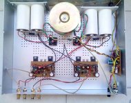
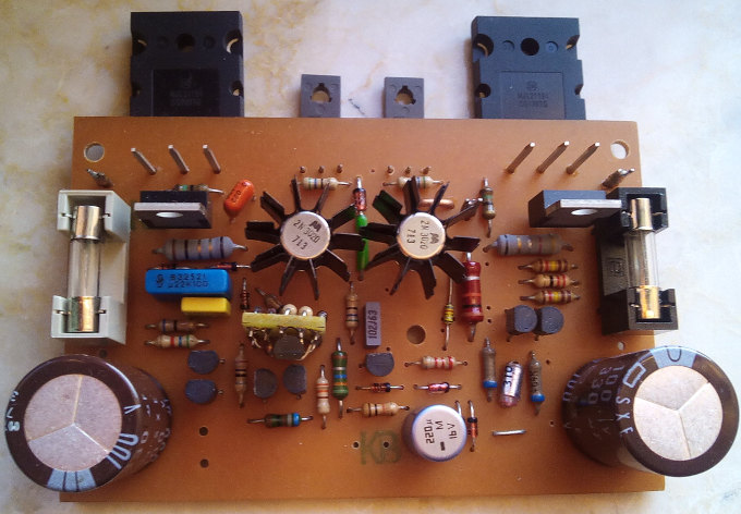
Thank you Daniel for input. My last build is using BC560C as input pairs, Moto 2N3020 (80Mhz version of 2N3019) as servos, Philips BD140's as drivers and MJL21194 as outputs. It is dead quiet when no signal applied but it is a roaring beast when it comes to do its job. When you see it is singing, you totally forget its bias cost. It is definitely worth to 200mA bias according to my last point of view. I believe that I could save extra 50-100mA with proper adjusting but I have no idea about which transistors are going to be reduced to its performance margins and no sure about the affects on all transistors are going to be equal. I could experiment on this subject later but no priority for now. One of my concern about bias was related with cooling because I'm using amplifier case as cooler. I'm using a bigger case (it is actually an electricity control panel cover) with many drilled holes now and heat dissipation and ventilation is quite sufficient.
My Darlington builds was sounding very good also but they weren't dead quiet that seems they required to rework the compensation. That's another thing that I learned according to my experience.
Attachments

Last edited:
Wow, that's good looking! I'm curious what's on the daughtercard?
Wow, that's good looking! I'm curious what's on the daughtercard?
Nice to see someone asked about it. Not just looking good, it sounds that good too

The daughtercard is a CCS module based on Elvee's schematic (3rd one, with zener) in place of R21. It just worked from first power on without any problem. Since the schematic is simple and straight forward, anyone can prepare it on a small piece of a proto board.
Last edited:
Cool, but the link doesn't work. What post # was that on?Nice to see someone asked about it. Not just looking good, it sounds that good too
The daughtercard is a CCS module based on Elvee's schematic (3rd one, with zener) in place of R21. It just worked from first power on without any problem. Since the schematic is simple and straight forward, anyone can prepare it on a small piece of a proto board.
- Home
- Amplifiers
- Solid State
- ♫♪ My little cheap Circlophone© ♫♪