Hello all!!!
I discovered the thread and the project just yesterday.
I was looking for a new amplifier to build, gave a rapid look to the original schematic and immediately felt in love with the Circlophone.
I really love its topology: simple, clean, extremely sophisticated but simple.
Great jod, Elvee.
I also have to clap my hands to danielwritesbac, for the big job he is doing dovumenting the project.
Wonderful project!!!
I immediately elect the Circlophone as my next DIY project.
After reading few pages of the thread, I decided it was time to simulate it, so LTspice entered.
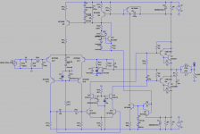
I drawn the circuit, play with it and now I have a nice circuit, slightly modified by me, that I'd like to submit to you.
I cascoded the inputs, just because I can, and because this will grant me to slap in my beloved 2SJ74 fet (or any other low voltage device), during the future tests.
I cascoded also the VAS stage; this way, the VAS transistors can be small signal transistors, as the cascode transistors will handle all the power dissipation.
This way I can also install the cascode transistors onto the same heatsink close to the driver transistors, compacting the board and saving the space otherwise occupid by the VAS heatsink.
Again, I added the CCS instead of R21,beause it seems to help.
Tonight I will leave for my holidays, which I will spend trekking through the alps; I will bhowever bring with me my laptop, so I can continue to play with the project and read the thread.
I want to develop my own PCB; I know there are already many, and really well done, but I want to do my own because it is funny, for me, and because in this way I can still learn.
I leave you with an image of my circuit and the simulation schematic.
Let me know if there is anyhing wrong with the circuit, what do you think and if you think what I've done is useless, and why.
Ciao,
Giovanni
I discovered the thread and the project just yesterday.
I was looking for a new amplifier to build, gave a rapid look to the original schematic and immediately felt in love with the Circlophone.
I really love its topology: simple, clean, extremely sophisticated but simple.
Great jod, Elvee.
I also have to clap my hands to danielwritesbac, for the big job he is doing dovumenting the project.
Wonderful project!!!
I immediately elect the Circlophone as my next DIY project.
After reading few pages of the thread, I decided it was time to simulate it, so LTspice entered.
I drawn the circuit, play with it and now I have a nice circuit, slightly modified by me, that I'd like to submit to you.
I cascoded the inputs, just because I can, and because this will grant me to slap in my beloved 2SJ74 fet (or any other low voltage device), during the future tests.
I cascoded also the VAS stage; this way, the VAS transistors can be small signal transistors, as the cascode transistors will handle all the power dissipation.
This way I can also install the cascode transistors onto the same heatsink close to the driver transistors, compacting the board and saving the space otherwise occupid by the VAS heatsink.
Again, I added the CCS instead of R21,beause it seems to help.
Tonight I will leave for my holidays, which I will spend trekking through the alps; I will bhowever bring with me my laptop, so I can continue to play with the project and read the thread.
I want to develop my own PCB; I know there are already many, and really well done, but I want to do my own because it is funny, for me, and because in this way I can still learn.
I leave you with an image of my circuit and the simulation schematic.
Let me know if there is anyhing wrong with the circuit, what do you think and if you think what I've done is useless, and why.
Ciao,
Giovanni
Attachments
Thanks for your kind words, GiovanniHello all!!!
I discovered the thread and the project just yesterday.
I was looking for a new amplifier to build, gave a rapid look to the original schematic and immediately felt in love with the Circlophone.
I really love its topology: simple, clean, extremely sophisticated but simple.
Great jod, Elvee.
I also have to clap my hands to danielwritesbac, for the big job he is doing dovumenting the project.
Wonderful project!!!
I immediately elect the Circlophone as my next DIY project.
You seem to follow very much the same path as Piersma: he also designed a "Super Circlophone", broadly along the same lines.After reading few pages of the thread, I decided it was time to simulate it, so LTspice entered.
I drawn the circuit, play with it and now I have a nice circuit, slightly modified by me, that I'd like to submit to you.
I cascoded the inputs, just because I can, and because this will grant me to slap in my beloved 2SJ74 fet (or any other low voltage device), during the future tests.
I cascoded also the VAS stage; this way, the VAS transistors can be small signal transistors, as the cascode transistors will handle all the power dissipation.
This way I can also install the cascode transistors onto the same heatsink close to the driver transistors, compacting the board and saving the space otherwise occupid by the VAS heatsink.
Again, I added the CCS instead of R21,beause it seems to help.
Tonight I will leave for my holidays, which I will spend trekking through the alps; I will bhowever bring with me my laptop, so I can continue to play with the project and read the thread.
I want to develop my own PCB; I know there are already many, and really well done, but I want to do my own because it is funny, for me, and because in this way I can still learn.
I leave you with an image of my circuit and the simulation schematic.
Let me know if there is anyhing wrong with the circuit, what do you think and if you think what I've done is useless, and why.
Ciao,
Giovanni
He was kind enough to send me a pair of boards, and it performs beautifully.
You can certainly inspire yourself from his work.
In case you didn't manage to dig his contribution out of this oversized thread, here it is:
http://www.diyaudio.com/forums/solid-state/189599-my-little-cheap-circlophone-122.html#post3697279
Elvee, I knew I liked this design but as I start to realize how this works, well now I'm starting to consider it as the closest solution to a long search I've been on. I've been looking for a non-switching Class AB without switching x-over distortion (whatever that means). I've sworn off LTPs for various reasons but the way they are employed here with insensitivity to device matching gets my thumbs us. It also avoids all the limitations of matching complementary devices at the output too.
However, I was also interested in a hybrid - tube VAS up front. I wonder if it would be possible to use this (circlophone) approach to realize a unity gain power buffer without gnf (except for the bias servos).
edit: p.s. can you post the LTSpice file for this ?
Hello all,
I'm back!
I took the time to read (most of) the thread, and now most of my doubts and questions have been answered.
I have to repeat I really love this amp, this seems to be the end of a long search, started some 25 years ago, when I built my first class AB amplifier (with TO3 2N3055!!!); from then, I searched for something that could join the class A "sound" (I built few Nelson Pass's Aleph 3/30 amplifier/prototypes, the first still in the '90s), with AB efficiency...
Up to now, no way, class A being too power-hungry for my taste, and class AB being "not exactly what I wanted" in terms of sound.
Of course I tried also valve amplifiers (KT88, EL34), which sound I appreciate, but I don't like them too much for the same reason of solid state class A amplifiers, power requirements.
I always knew that there should be a clever way to keep those output transistor always on, without transforming enormous quantity of energy into heat.
I also tried to develop complex bias servos, to obtain that, but never really succeded.
And then I found your Circlophone. Great.
I decided to use what I have on hand,so fets on input and as a ccs.
Please find the schematic attached.
It simulate very well.
Any problem you can see with my solution?
any suggestion?
I also own several 2SK1058 FETs, do you think I can try them as output device?
Any improvement over BJTs?
Next step is to develop a suitable PCB, in the next few days.
I will let you know.
I'd like to read it too, if you can send it to me.
Ciao,
Giovanni
I'm back!
I took the time to read (most of) the thread, and now most of my doubts and questions have been answered.
I have to repeat I really love this amp, this seems to be the end of a long search, started some 25 years ago, when I built my first class AB amplifier (with TO3 2N3055!!!); from then, I searched for something that could join the class A "sound" (I built few Nelson Pass's Aleph 3/30 amplifier/prototypes, the first still in the '90s), with AB efficiency...
Up to now, no way, class A being too power-hungry for my taste, and class AB being "not exactly what I wanted" in terms of sound.
Of course I tried also valve amplifiers (KT88, EL34), which sound I appreciate, but I don't like them too much for the same reason of solid state class A amplifiers, power requirements.
I always knew that there should be a clever way to keep those output transistor always on, without transforming enormous quantity of energy into heat.
I also tried to develop complex bias servos, to obtain that, but never really succeded.
And then I found your Circlophone. Great.
I decided to use what I have on hand,so fets on input and as a ccs.
Please find the schematic attached.
It simulate very well.
Any problem you can see with my solution?
any suggestion?
I also own several 2SK1058 FETs, do you think I can try them as output device?
Any improvement over BJTs?
Next step is to develop a suitable PCB, in the next few days.
I will let you know.
hi bigun I have an article from ww world dec 1999 you might like to view. New Class AB power amp eliminating cross over distortion.
I'd like to read it too, if you can send it to me.
Ciao,
Giovanni
Attachments
It looks finePlease find the schematic attached.
It simulate very well.
Any problem you can see with my solution?
You can probably eliminate C9, with your components and configuration, local instabilities won't be an issue.any suggestion?
Also, I suppose you are aware that the 2N2907's as drivers are a bit small, and in reality they would at least require a good heatsink
You can, but in this case I would recommend you build an opposite polarity version, this will eliminate the need for drivers.I also own several 2SK1058 FETs, do you think I can try them as output device?
This has been described somewhere in thread, certainly for darlington OP's, and perhaps also for MOSfets, I don't quite remember
The slew rate will probably be improved, maybe the harmonic profile too, but the global THD will probably increase a bit, because the loop gain will be diminished.Any improvement over BJTs?
Another effect will be a reduced positive swing compared to BJT's.
This could be eliminated by using the same technique as in the CircloMOS, but I am not sure how the circlophone and circloMOS bias schemes will coexist.
Something to be tried
Member
Joined 2009
Paid Member
hi bigun I have an article from ww world dec 1999 you might like to view. New Class AB power amp eliminating cross over distortion.
Can you send me a copy ?
Hello,hi bigun I have an article from ww world dec 1999 you might like to view. New Class AB power amp eliminating cross over distortion.
Is it possible to make it public, so anyone can read it?
Thanks and regards.
Hello all,
I'm working on my own PCB, with jfet cascoded inputs.
I simulated my jfet version of the circlophone, and modified slightly the input stage and feedback path, increasing their impedance.
Is there any problem increasing the feedback path as shown?
I think everything works fine, but I have to ask before to proceed with the PCB.
In the past, I built a Nelson Pass amplifier with a jfet input (Aleph J), and completely removedthe capacitor in the feedback path (C3 in original Circlophone schematic).
In such a cas, the R16 feedback resistor should be connected directly to ground.
Is it feasible?
Simulating my circuit in such a condition gives a slightly higher DC offset at the output (about 2.6mV), what about in reality?
Do I have to match input jfets to obtain an usable offset?
Or simply this does not work?
I also removed the input capacitor, cause I'd like to use two very big polypropilene motor capacitor I own, that cannot fit onto the PCB (Arcotronics MKP C.4G, 5uF, 700V).
Is this OK?
I'm also wondering if I can omit them completely; any issue (other than the usuals) running this topology without input capacitor?
I cannot see any, but I'm not skilled as you.
I have a lot of 1N5822 diodes on hand, could I use two of them paralleled for each rail, just to be sure they can handle the rated output current?
Using them in parallel would reduce the total forward voltage, but this shouldn't be an issue, isn't it?
Again, I omissed the compensation ntwork on LTP (C6, R23); do I need it in reality? jfets I think should not need it.
What's your thought?
Last (for now) question: somewhere in the thread you (Elvee) mentioned that one could use a schottky diode instead of the BAT... device (D7); is it true?
Could I use something like a 1N5817?
I simulated it and it seems to work fine, even under heavy clipping.
Thank you in advance,
Giovanni
Attachments
It is still practicable, but marginal: at this level of impedance, noise and hum pickup issues will begin to appear.I simulated my jfet version of the circlophone, and modified slightly the input stage and feedback path, increasing their impedance.
Is there any problem increasing the feedback path as shown?
You will need to be very careful with your construction techniques.
Anyway, if you encounter too many difficulties, it is easy to revert to more reasonable values
YesIn the past, I built a Nelson Pass amplifier with a jfet input (Aleph J), and completely removedthe capacitor in the feedback path (C3 in original Circlophone schematic).
In such a cas, the R16 feedback resistor should be connected directly to ground.
It is feasible, but you will need to match the Fets with great accuracy.Is it feasible?
Simulating my circuit in such a condition gives a slightly higher DC offset at the output (about 2.6mV), what about in reality?
Do I have to match input jfets to obtain an usable offset?
Compared to BJT's, FETs have a much wider dispersion, which means you will have to process and sort a huge number of parts to find a suitable pair.
That could mean a hundred or more.
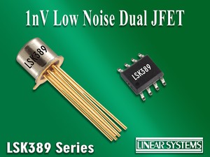
A better option would be to use of a dual FET, preferably monolithic
You are looking for problems there: using such a preposterously large, high voltage component where a mere 16V is sufficient can only bring problems: it will act as an electrostatic antenna, meaning it will pickup the hum generated by any "hot" conductor or component in the vicinity: everything related to the power transformer for example.I also removed the input capacitor, cause I'd like to use two very big polypropilene motor capacitor I own, that cannot fit onto the PCB (Arcotronics MKP C.4G, 5uF, 700V).
Is this OK?
In practice, you will need to enclose it in a shielding can, but this brings issues of its own: an increased capacitance to ground.
In addition, because the capacitor is bulky, the input wiring will have to enclose a significant area, meaning sensitivity to stray magnetic fields too.
I'd recommend you use a low voltage film cap, PP if you absolutely want it, but preferably PETP (mylar).
In a coupling role, it is perfectly sufficient and won't have the slightest impact on the reproduction quality.
You will then end up with a DC-coupled amplifier.I'm also wondering if I can omit them completely; any issue (other than the usuals) running this topology without input capacitor?
I cannot see any, but I'm not skilled as you.
That is possible, but difficult and you will need a good speaker protection system in case something wrong, which can happen very easily.
In your case, a single device is sufficient, but there is no inconvenient paralleling themI have a lot of 1N5822 diodes on hand, could I use two of them paralleled for each rail, just to be sure they can handle the rated output current?
Using them in parallel would reduce the total forward voltage, but this shouldn't be an issue, isn't it?
Unlike the previous one, this version has a severely negative phase margin above 1MHz. This means that in reality, it will oscillate like madAgain, I omissed the compensation ntwork on LTP (C6, R23); do I need it in reality? jfets I think should not need it.
What's your thought?
The BAT54 is a schottky diode, but it is a small, signal one. The 1N5817 is a power one, with a much larger junction area and a lower Vf, and this will probably interfere with the circlophone engine.Last (for now) question: somewhere in the thread you (Elvee) mentioned that one could use a schottky diode instead of the BAT... device (D7); is it true?
Could I use something like a 1N5817?
It has been tried earlier in the thread, and there were problems.
Signal schottky's are plentiful, and less expensive than larger ones. There is no reason not use them. BAT85 or 86 are also suitable, as are many tens of types.
Just look for any 20V to 50V, 50mA to 300mA model.
Attachments
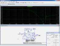
Unlike the previous one, this version has a severely negative phase margin above 1MHz. This means that in reality, it will oscillate like mad
Wow.
Now, please, explain me how you did it into LTSpice; I know how to use it, but I'm not very expert, and this is a thing I can't do...
And, the reason?
Is it because I removed the feedback capacitors?
LSK489?
Would you recommend something like the LSK489 ?
Hello, Elvee.Yes
It is feasible, but you will need to match the Fets with great accuracy.
Compared to BJT's, FETs have a much wider dispersion, which means you will have to process and sort a huge number of parts to find a suitable pair.
That could mean a hundred or more.
A better option would be to use of a dual FET, preferably monolithic.
Would you recommend something like the LSK489 ?
Last (for now) question: somewhere in the thread you (Elvee) mentioned that one could use a schottky diode instead of the BAT... device (D7); is it true? Could I use something like a 1N5817?
A word about D6/D7: if the BATxx is not available, a possibility is to replace both diodes by fast 1A ones like BYD33, BYV26, UF4004, etc. This combination will be equivalent to 1N4148+BAT85 (Do not use schottkies!!!)
There are a number of techniques for measuring the loop gain.Wow.
Now, please, explain me how you did it into LTSpice; I know how to use it, but I'm not very expert, and this is a thing I can't do...
The most basic are explained in the "Educational" part of LTspice, see the files extracted below.
To progress further, you can search the forum with the terms "probe" "tian" "middlebrook" "GFT" "gain" "loop"
It is probably related, but there might be additional factorsAnd, the reason?
Is it because I removed the feedback capacitors?
Yes that is the kind of component, except that for Croco, P types are required.
Note that even for high quality monolithic types like these, the offset equivalent is 20mV. That would translate into more than 400mV output offset for a DC-coupled amplifier
Thaks for the reminder
Attachments
Last edited:
Thanks for the info.Yes that is the kind of component, except that for Croco, P types are required.
Note that even for high quality monolithic types like these, the offset equivalent is 20mV. That would translate into more than 400mV output offset for a DC-coupled amplifier

Actually I was referring to Piersma's Inverted JFET Circlophone circuit (post #331) that's using a pair of 2SK170 (N-channel) and final version of his board (post #1212).
Thanks again!
")
Hello,
I modified (my) schematic, reverting back to original values and adding compensation networks...
I also added the Piersma input stage buffers, which I lke very much; of course I've used P jfet, cause in this way I can continue to use my output NPN transistors.
About the phase shift, I can't understand totally; if I simply replace my transistors models (2SC2911, 2SA907, 2SC2240, etc.) with LTspice standard library components, it seems to disappear, or at least to reduce a lot.
Probably my models are not correct.
Well, I will simulate with standard parts and will try in reality with differnet transistors.
We will see.
Attached latest schematic.
I hope this is the right one, I will proceed now with the PCB.
Ciao,
Giovanni
Attachments
OK, forget my previous post attachment.
It doesn't work as expected.
Decided to remove the input CFP.
Here attached the last iteration...
[EDIT] Nothing else than the original with Jfet inputs...
And a different CCS.
It doesn't work as expected.
Decided to remove the input CFP.
Here attached the last iteration...
[EDIT] Nothing else than the original with Jfet inputs...
And a different CCS.
Attachments
Last edited:
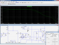
When you use the simplified probe, you have to make sure the driving side has a negligible impedance, and the input side an ~∞ one, otherwise you have to use all the terms of the transfer matrix, to take into account the loading effect.
You can place it in series with the feedback resistor, but on the output side, to satisfy the above condition, see below
You could also place it in series with the jFET's gate, but if it has a high capacitance, it could make the result unreliable at high frequencies.
You can place it in series with the feedback resistor, but on the output side, to satisfy the above condition, see below
You could also place it in series with the jFET's gate, but if it has a high capacitance, it could make the result unreliable at high frequencies.
Attachments
Hello Elvee,
Thank you for your explanation, I'm quite a noob in using LTspice...
I'm still learning.
If you don't mind, and if you have time to spend, I'll ask for your help in the future...
Even more, I'm a 44 years old ELECTRIC engineer, not electronic, and I'm a self-made electronic enthusiast.
So, be patient with me.
Ciao
Hello all,
I just finished to draw the PCB for my variation of the Circlophone, the Jfet one.
Please find here attache a schematic, a PCB in .pdf format and a .zip format with the Cadsoft Eagle project files.
Hope you like it, and please let me know any errors, doubt or improvement I can add.
Ciao,
Giovanni
I just finished to draw the PCB for my variation of the Circlophone, the Jfet one.
Please find here attache a schematic, a PCB in .pdf format and a .zip format with the Cadsoft Eagle project files.
Hope you like it, and please let me know any errors, doubt or improvement I can add.
Ciao,
Giovanni
Attachments
- Home
- Amplifiers
- Solid State
- ♫♪ My little cheap Circlophone© ♫♪