There are several radio transmitters and many other RF sources. But also that the inbuilt radio beats one signal against the other when working and that receiver is directly attached to the input of the amplifier.Do you use it with a radio transmitter?
Everything directly below the pitch for the cap? No idea why. We wouldn't short the R in the RC of a woofer because that couldn't filter sufficiently. As far as I know, low pass filters work similarly, no matter if AF or RF. So, maybe an actual filter can work better than just a cap? I'm not an expert, so I can't explain it.Why would the cap increase the amplitude?
Thank you!! Now, I have marked the schematic more generically "BAT8x Schottky" for D7 and that helpful step has conquered the come and go availability problem of individual part numbers. Does it need a voltage spec added?. . . better stick with BAT8x types.
As for the BIG Schottky D4, D5, I'm glad that we didn't have to specify 80SQ045NG or STPS5L60 or an even larger "Solar Power" model for very low voltage drop. Performance like the Motorola in your photograph is rare. I have simply marked the schematic as "5A Schottky" but I need to know if 5a is insufficient. Does it need a voltage spec added?
Moderately, since we're close enough for most speakers but not all?I do not see how this [safety auto adapt power supply current to suit speaker load] could be implemented without huge complications.
1). Kenwood shows the use of a 4 conductor ribbon (or for CT that is 1 large 0v and 2 small voltage) current dumper cable of about 10" long, and that's not very active when 8 ohm speaker load but really cuts the power with a 4 ohm speaker load. I'm not suggesting overdo, just consideration.
2). Tube amplifiers and any favored guitar amplifier use a CRC and in this case the "R" is also a current dumper. A slightly bigger "R" is a "mild" protection against unexpected loads. This can allow diode and transistors in the amplifier to momentary operate in their peak area but as soon as the cap is run out, the resistor holds back current momentarily and somewhat helps prevent exploded output devices. It seems that the cRc is worth considering. Unfortunately, I can't guess the most helpful value for "R"
Here's the parts list progress so far:
Q5/Q6 2N1893, 2SD669, 2SC2238, 2SC5171, MJE340?
Q8/Q10 MJL21194, MJW21196
Q9/Q11 2SB649, 2SA968, 2SA1930, MJE350
Q12/Q13 2SC1845, KSC1854F
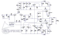
And here is the "extra power Circlophone" schematic progress so far:
Attachments
That could be a problem, if they are very close, high power and fall in problematic frequency bands.There are several radio transmitters and many other RF sources.
That should not be a problem: if the local oscillator's leakage is sufficient to create enveloppe rectification, you have a real problem -in your tuner-But also that the inbuilt radio beats one signal against the other when working and that receiver is directly attached to the input of the amplifier.
It is a filter, with a R and a C. First order.Everything directly below the pitch for the cap? No idea why. We wouldn't short the R in the RC of a woofer because that couldn't filter sufficiently. As far as I know, low pass filters work similarly, no matter if AF or RF. So, maybe an actual filter can work better than just a cap?
This kind of filter is incapable of playing tricks (not 100% true, but true enough in this case, the exceptions being lab curiosities more than anything else)
No, the max. they will ever see is 1V or so.Does it need a voltage spec added?
For normal load impedances (down to 2 ohm), a generic schottky of 5A rating is sufficient.As for the BIG Schottky D4, D5, I'm glad that we didn't have to specify 80SQ045NG or STPS5L60 or an even larger "Solar Power" model for very low voltage drop. Performance like the Motorola in your photograph is rare. I have simply marked the schematic as "5A Schottky" but I need to know if 5a is insufficient. Does it need a voltage spec added? Moderately, since we're close enough for most speakers but not all?
Here again, the reverse voltage is negligible.
For very low output impedances, 1 ohm and below, a bigger type would become necessary.
All of this seems to emulate the effect of a cheapo, undersized transformer, whose voltage is sagging under heavy loads.1). Kenwood shows the use of a 4 conductor ribbon (or for CT that is 1 large 0v and 2 small voltage) current dumper cable of about 10" long, and that's not very active when 8 ohm speaker load but really cuts the power with a 4 ohm speaker load. I'm not suggesting overdo, just consideration.
2). Tube amplifiers and any favored guitar amplifier use a CRC and in this case the "R" is also a current dumper. A slightly bigger "R" is a "mild" protection against unexpected loads. This can allow diode and transistors in the amplifier to momentary operate in their peak area but as soon as the cap is run out, the resistor holds back current momentarily and somewhat helps prevent exploded output devices. It seems that the cRc is worth considering. Unfortunately, I can't guess the most helpful value for "R"
If that's really what you want to achieve, you'd better go for the real thing: it will be simpler and cheaper than starting with a good supply in the first place.
I would leave the MJE340 out of the list: it works, but it is not optimal, and when combined with other suboptimal components, it could begin to cause troubles.Here's the parts list progress so far:
Q5/Q6 2N1893, 2SD669, 2SC2238, 2SC5171, MJE340?
Q8/Q10 MJL21194, MJW21196
Q9/Q11 2SB649, 2SA968, 2SA1930, MJE350
Q12/Q13 2SC1845, KSC1854F
At extremes, the datasheet on this 200va 28+28vac transformer says it "ducks" down to a 26.5+26.5vac transformer: http://www.antekinc.com/pdf/AS-2228.pdf I didn't need the 300va. Thank you for saving me $10!!
") All of the current dropping is modest and slight and the CRC prevents noise and prevents extraneous workload. Much of that work could be done by cabling, but my radio, aka "Monobloc Powered Speaker" has only very short length cables. I hope that the tiny loss from the speaker jack fuse is okay.
All of the current dropping is modest and slight and the CRC prevents noise and prevents extraneous workload. Much of that work could be done by cabling, but my radio, aka "Monobloc Powered Speaker" has only very short length cables. I hope that the tiny loss from the speaker jack fuse is okay.
So, instead of blowing the speaker jack fuse. . .
To work my extremely simple "gain nipper" circuit's hand made optoisolators, I need to know the permissible range of gain for Circlophone.
The gain nipper can also be worked by Rod Elliot's clip detector Power Amp Clipping Indicator See how it uselessly lights up an LED? That could light up an optoisolator instead.
I think it is doable without that circuit when the speaker load is known, since clipping output is obviously more powerful than normal output.
Probably an optoisolator can be powered directly from a voltage divider at amplifier output, really similar to a headphone jack hookup. Just divide a predetermined safety limit down to led switch on voltage for powering up the gain nipper's LED with enough current for up to 40% of LED tolerance at most. Its about $1 per gain nipper. Again, really no noise when it isn't on. The optoisolator is bypassed by an ordinary resistor and simply changes that resistor value mildly, decreasing output power during emergency conditions.
For example R17=8.2k series to 2.7k//optoisolator.
And then the really loud car insurance commercial doesn't destroy the amplifier.
See? I believe in protection circuits that remove noise. Each little tiny step is mild and adjustable.
Perhaps this can be streamlined a bit more?
Total added parts so far = 2 big resistors, 2 big caps at the power supply to add CRC, 1 fuse at the speaker jack, and then 3 resistors 1 led and 1 photocell for gain nipper. EDIT: Perhaps the gain nipper could be refined by simply using a zener for voltage excess detector and then there isn't a voltage divider at amp output but rather just powering the led by zener series to resistor series to LED?
So that line was changed to look like this:
Q5/Q6 2N3019 for rails < 40v, else 2N1893
With 2N3019 and 2N1893, there is sufficient availability to remove the less optimal alternates. Thanks again!
I'll be using a high end instrument amp type power supply that doesn't abuse a small transformer, because the actual point is to track the MJL21194 datasheet SOA difference between peak and constant output. A benefit is that this arrangement doesn't sound like it has a small transformer.All of this seems to emulate the effect of a cheapo, undersized transformer, whose voltage is sagging under heavy loads. If that's really what you want to achieve, you'd better go for the real thing: it will be simpler and cheaper than starting with a good supply in the first place.
All of the current dropping is modest and slight and the CRC prevents noise and prevents extraneous workload. Much of that work could be done by cabling, but my radio, aka "Monobloc Powered Speaker" has only very short length cables. I hope that the tiny loss from the speaker jack fuse is okay.So, instead of blowing the speaker jack fuse. . .
To work my extremely simple "gain nipper" circuit's hand made optoisolators, I need to know the permissible range of gain for Circlophone.
The gain nipper can also be worked by Rod Elliot's clip detector Power Amp Clipping Indicator See how it uselessly lights up an LED? That could light up an optoisolator instead.
I think it is doable without that circuit when the speaker load is known, since clipping output is obviously more powerful than normal output.
Probably an optoisolator can be powered directly from a voltage divider at amplifier output, really similar to a headphone jack hookup. Just divide a predetermined safety limit down to led switch on voltage for powering up the gain nipper's LED with enough current for up to 40% of LED tolerance at most. Its about $1 per gain nipper. Again, really no noise when it isn't on.
The optoisolator is bypassed by an ordinary resistor and simply changes that resistor value mildly, decreasing output power during emergency conditions. For example R17=8.2k series to 2.7k//optoisolator.
And then the really loud car insurance commercial doesn't destroy the amplifier.
See? I believe in protection circuits that remove noise. Each little tiny step is mild and adjustable.
Perhaps this can be streamlined a bit more?
Total added parts so far = 2 big resistors, 2 big caps at the power supply to add CRC, 1 fuse at the speaker jack, and then 3 resistors 1 led and 1 photocell for gain nipper. EDIT: Perhaps the gain nipper could be refined by simply using a zener for voltage excess detector and then there isn't a voltage divider at amp output but rather just powering the led by zener series to resistor series to LED?
Thank you! I would also like to leave sub optimal parts off the list.I would leave the MJE340 out of the list: it works, but it is not optimal, and when combined with other suboptimal components, it could begin to cause troubles.
So that line was changed to look like this:
Q5/Q6 2N3019 for rails < 40v, else 2N1893
With 2N3019 and 2N1893, there is sufficient availability to remove the less optimal alternates. Thanks again!
Last edited:
So, how much voltage is coming out of Circlophone when it has powered a 4 ohm speaker to 150 watts?
I don't need to sag the rails. All I really needed to do is gently, proportionately turn down the gain upon output voltage higher than. . . ?
EDIT:
The limiter prospect is really similar to powering lightspeed attenuator by a zener (what voltage?) at speaker output.
I don't need to sag the rails. All I really needed to do is gently, proportionately turn down the gain upon output voltage higher than. . . ?
EDIT:
The limiter prospect is really similar to powering lightspeed attenuator by a zener (what voltage?) at speaker output.
When I talk of undersized transformer, I mean really undersize: like 100VA or less for a 100W amp.At extremes, the datasheet on this 200va 28+28vac transformer says it "ducks" down to a 26.5+26.5vac transformer: http://www.antekinc.com/pdf/AS-2228.pdf I didn't need the 300va. Thank you for saving me $10!!
I'll be using a high end instrument amp type power supply that doesn't abuse a small transformer, because the actual point is to track the MJL21194 datasheet SOA difference between peak and constant output. A benefit is that this arrangement doesn't sound like it has a small transformer.
That will seriously sag under load.
What is the "sound of a small transformer", and how could you differentiate it from an impedance limited supply?
You are of course free to add any compressor, limiter, ALC, etc, to your Circlophone, but I don't think this thread is the kind of place to discuss such devices: they are totally unspecific, and can be part of any amplifier or effect box.
......./...........
Perhaps this can be streamlined a bit more?
Total added parts so far = 2 big resistors, 2 big caps at the power supply to add CRC, 1 fuse at the speaker jack, and then 3 resistors 1 led and 1 photocell for gain nipper. EDIT: Perhaps the gain nipper could be refined by simply using a zener for voltage excess detector and then there isn't a voltage divider at amp output but rather just powering the led by zener series to resistor series to LED?
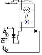
If you want some simple and safe limiter that does not kill too much the performances, you can add a big, low-voltage light bulb in series with the output, but inside the feedback loop.
The same with the fuse or any other overcurrent protection device.
Placing them outside the loop will ruin the performances and the damping factor.
A clipping detector can easily be added at the phase-splitter level: when any of the bases drop below 1.2V, the amp is clipping.
You just need two transistors, two resistors and an ORing circuit to detect when any of the transistors is off.
Any gain variation should be done at the input: messing up with the closed loop gain is rarely a good idea, in any amplifier.
Thank you for the guidance. I especially appreciate that the project is inspirationally doable together with great published results.
I have a somewhat "modern problem," such as popular since about March of 1992 and persisting even more popular in 2012.
A normal home computer, maxed out plus clipping, still cannot push a 21db gain power amp to 100w@8R with decent fidelity. Likewise my CD player has a VCA/Digital volume control that clips itself and/or sounds horribly compressed if run to max. RMAA, Rightmark Audio Analyzer confirms that these devices aren't capable of traditionally high output but rather conform to the modern standard.
Which of the following remedies do you suggest?:
1). Insert quality decreasing preamplifier between modern source and Circlophone? or
2). Increase gain for Circlophone to meet potential and work with modern sources?
I sure would like your recommendation for a good solution.
I don't know exactly how to go about it.Any gain variation should be done at the input
I have a somewhat "modern problem," such as popular since about March of 1992 and persisting even more popular in 2012.
A normal home computer, maxed out plus clipping, still cannot push a 21db gain power amp to 100w@8R with decent fidelity. Likewise my CD player has a VCA/Digital volume control that clips itself and/or sounds horribly compressed if run to max. RMAA, Rightmark Audio Analyzer confirms that these devices aren't capable of traditionally high output but rather conform to the modern standard.
Which of the following remedies do you suggest?:
1). Insert quality decreasing preamplifier between modern source and Circlophone? or
2). Increase gain for Circlophone to meet potential and work with modern sources?
I sure would like your recommendation for a good solution.
Last edited:
Make a variable input divider, like in this example.I don't know exactly how to go about it.
For an inverted control polarity, swap R19 and the LDR (and shunt it with a suitable resistor)
As published, the Circlophone has a default gain of 27dB. That's 6dB better than 21dB. Add another 6dB because you build a 4ohm version, you are 12dB better. If it is still insufficient, you can easily increase the gain by changing R17 to 15K or 22K.I have a somewhat "modern problem," such as popular since about March of 1992 and persisting even more popular in 2012.
A normal home computer, maxed out plus clipping, still cannot push a 21db gain power amp to 100w@8R with decent fidelity.
Increasing the gain poses little problem, decreasing it could be problematic.
The stability has been tested down to a gain of 8, I think 5 would still be possible, but this has not been tested.
Here are two possibilities of clipping detection.
The hard clipping detection (left) is specific to the Circlophone, the warning (right) is "agnostic" and could be used with any amplifier.
It has the advantage of taking into account the actual rail voltages.
In this case, the warning flag is raised when the output is closer than ~4V of either supply rail, but this can be easily adapted by changing the zeners voltage
Attachments
Prosound Circlophone? Wow!!!
Wow, I'm so excited!
Your version of the early clip warning is so much more elegantly streamlined than I've ever seen before.
I have some notes. . .
The optocoupler's inbuilt LED (very low current tolerance) would appreciate a series resistor, possibly fantastic as a variable resistor dial. It is also nice to add an ordinary LED series to the optocoupler's inbuilt LED, flashing correspondingly to the LED inside of the optocoupler, thus facilitating easy adjustments and a taller knee voltage to help prevent nuisance activation. A small value zener could be added series to the LED, if necessary for tolerances. With the clipnipper, I had only intended to make mildly proactive vu meter, but you changed the whole prospect into a soft clip amp. WOW!!! THANKS!!!
Clipping is an outdated notion. That's amazing!
The "extra power" Circlophone, now that you have equipped it with soft clip, as if a tube amp with border blasters, it is different than most of solid state amplifiers. Of course, on a never-clipping amplifier, I could make a more sensible transformer voltage choice, such as a step smaller transformer which may make up to 39vdc+39vdc and also use very sturdy rails, and yet still enjoy the more powerful amplifier's greater amount of more useful output. How very elegant! Thanks again!
. . . and a few questions.
I'm not great with math, and so need to ask: What feedback resistor value results in a gain of 8 for Circlophone?
MBR745 7.5a 45v diode datasheet says same vdrop graph as MBR735 7.5a 35v diode. Is the voltage a concern?
Which PCB has no errors but also the best layout?
Last edited:
The schottky's role is minor, they simply improve the energetic efficiency and could be omitted without problem, there is no need for high performance there.
I'm about to alter @powerflux pcb with minor changes. One of altered pcb may not use the schottkys on each rail due to space requirements. If it is not a compromise with sound quality, power efficiency is not a deal for me. So, can we omit 1R and 0R5 respectively in this situation?
An optocoupler doesn't have a particularly low current tolerance: the 4N25 in example tolerates 60mA of continuous current and 3A surge. Probably more than a general purpose LED..
The optocoupler's inbuilt LED (very low current tolerance) would appreciate a series resistor, possibly fantastic as a variable resistor dial.
Anyway, the optocoupler's presence only serves to illustrate the output of the detector, and it could be replaced by any current sensitive device (or an LDR-based opto)
.It is also nice to add an ordinary LED series to the optocoupler's inbuilt LED, flashing correspondingly to the LED inside of the optocoupler, thus facilitating easy adjustments and a taller knee voltage to help prevent nuisance activation
That is certainly an option, and a visible LED certainly does offer a plus, even if it is hidden from the final user, but adjustment is not required: the left part detects when the amp runs out of steam, and the right part reacts somewhat before, but also at a well pre-defined threshold.
That will only change the current in the LED when the circuit is active, not the threshold.A small value zener could be added series to the LED, if necessary for tolerances.
Here, for the example I have chosen a 5mA current, but other values are possible.
There is probably no need to reinvent the wheel: I remember that ~35years ago, Peavey already made amplifiers that were "unsaturable".With the clipnipper, I had only intended to make mildly proactive vu meter, but you changed the whole prospect into a soft clip amp. WOW!!! THANKS!!!
My memory is failing, but other members could probably give you details, and pointers to practical, proven solutions.
470*(8-1)=3K3. . . and a few questions.
I'm not great with math, and so need to ask: What feedback resistor value results in a gain of 8 for Circlophone?
Not at all, you could use a 2V one, if you could find it...MBR745 7.5a 45v diode datasheet says same vdrop graph as MBR735 7.5a 35v diode. Is the voltage a concern?
Wakibaki's is proven, as is Powerflux's, Heinz came up with something promising, but I don't think it has actually been tested yet, and Mickeymoose current version (not released though) is good, and his next version promises to be better....Which PCB has no errors but also the best layout?
Make your choice
The schottky's are (sort of) optional, but the resistors aren't: they sense the current for the bias servo, and if you omit them, your amp will be destroyed in milliseconds.I'm about to alter @powerflux pcb with minor changes. One of altered pcb may not use the schottkys on each rail due to space requirements. If it is not a compromise with sound quality, power efficiency is not a deal for me. So, can we omit 1R and 0R5 respectively in this situation?
You can leave them, and just omit the schottky's: that won't lead to an instant disaster.
However, this might not be as attractive as it looks: on a 4Ω load, the output voltage will be amputated of ~25% (due to the 1Ω, but when it clips on one side, there is no point going further on the other).
This will divide the output power by 1.25²: more than 1.5.
If this is not bad enough, the power not dissipated in the load will be by the resistor: this could easily reach 20W or more, depending on the amplifier's power.
A 20W resistor is not exactly a space-saving option...
Last edited:
Daniel...
I built a similar Circlophone to the one you plan to.
Mine runs on (has been for a few months, I think) +-40V rails, adequate heatsink+fan cooling.
The semiconductors I use are BC546/556 "C" suffix (highest hfe), 2N3019 (not heatsinked - no issues) 2SB649A, and MJW21196. The outputs (MJW) are a beastly kind, just like the ones you are going to use. With the supply voltage I use I know I can pump out plenty of power into 4 ohms and not worry about anything with these transistors. Good choice. Two transistors, Q12 and Q13 (going off of Elvee's original schematic) I changed to KSC1845F becase of the higher supply voltage. These transistors have a different pinout and the pins were bent to compensate for the PCB.
I matched (within +-2 hfe) and thermally coupled the input pair with a tiny zip tie and thermal compound. I have <0.1mV of DC offset. I used 1% 1/4W metal film resistors throughout. I used polystyrent for the input low pass capacitor (C5) and C12 (I used 270pF in both places). I used polypropolene 1.5nF for C6 and I did use C11, polypropolene 10nF.
I used the wakabaki PCB. The only issue it has is an extremely minor one, not even an issue at all in my opinion. One of the capacitors on the board (they are all 3 pads to allow use for small or large ones) is missing a connection between two of its pads, the one designating the smaller capacitor option is connected while the one designating the larger option is not, although this is only 2 or 3 millimeters of distance. I just used a bit extra solder to join the two. I had to drill slightly larger holes for the two large schottkys. The way the output on the board is set up in my opinion is not the best due to small size holes, but it does just fine. I use small length wires (~1 inch) from PCB to output transistors. I monitored the unit on a scope through a few conditions and did not see any hint of an issue. I did not drive it with a square wave into a capacitive load however, but I have been using it extensively for a bit of time now.
My Circlophone is extremely dead silent. If it wasn't for the fan in the case I wouldn't know whether it was on or off, even with my ear right against a tweeter. If i recall from reading this thread the Powerflux one may need to be slightly modified regarding a filter due to HF noise pickup. I still have PDF's created from the wakabaki gerber files made to print to scale. I posted them pages ago.
------Elvee, what's this about C11 not required for the outputs I'm using? I take it this has been tested? If so, I may remove them. Although, I may not. Why mess with something that is already good.
Schottky reverse voltage is irrelevant here.
We are only using them in forward bias.
R16 and R19 = 1K2?
I don't think you want to mess with 10Ks.
----
This was reply to #450. several new posts
have appeared while I was typing... Or
perhaps I didn't notice the new page.
We are only using them in forward bias.
R16 and R19 = 1K2?
I don't think you want to mess with 10Ks.
----
This was reply to #450. several new posts
have appeared while I was typing... Or
perhaps I didn't notice the new page.
Last edited:
470*(8-1)=3K3
You want a 3K3 input impedance?
No sir, that's not the intent. I just needed the documentation of both high and low points of reference, because I wish to avoid exceeding that range. My limiter and Elvee's elegantly streamlined soft clip do both momentarily change amplifier settings, but that occurs only for a brief instant and only when needed. In trade, I was able to choose a more orthodox transformer voltage.You want a 3K3 input impedance?
Although such technology has existed in the past, the new presentations are much different because they are extremely doable and because they both have a "tump the zener" function to make sure that they stay "off" until they are needed to block clipping or maintain SOA. It is the "doable" aspect, together with the low cost, that makes clipping an outdated notion of the past. A simple thermal resistor, just 1 more part, could add a further elegance and function to the protection, yet still maintain the low cost, simplicity, and high performance. I appreciate that these easy systems are readily adjustable. Their effect on audio is momentary, rare, and good, since it is better than either exploded output devices or clipping.
The unorthodox possibility is a somewhat more like a 25w soft clip Circlophone outperforming a "standard" 60w amplifier.
Last edited:
C11 is necessary when very fast output transistors are used. In your case, it is not necessary, but it does little harm.------Elvee, what's this about C11 not required for the outputs I'm using? I take it this has been tested? If so, I may remove them. Although, I may not. Why mess with something that is already good.
If you remove it, the transient response will be infinitesimally cleaner, but otherwise the effect is barely noticeable.
In general, I prefer to leave the impedances seen by the LTP more or less constant, so that minor poles are not disturbed, but in this case, 1K2 would work without problem.R16 and R19 = 1K2?
I don't think you want to mess with 10Ks.
No, that's the value of the feedback resistor for a gain of 8.You want a 3K3 input impedance?
With your supply, transistors, and on a 4 ohm load, you run no risk of exploding your OP devices.Their effect on audio is momentary, rare, and good, since it is better than either exploded output devices or clipping.
If you try to abuse it, you will probably damage your speaker, but not the amplifier.
I recommend you first try to build the naked Circlophone, and you add your bells and whistles later (and incrementally), when you're satisfied everything works fine.
Otherwise, there is a risk all ends in a big mess for unclear reasons.
Although such technology has existed in the past, the new presentations are much different because they are extremely doable and because they both have a "tump the zener" function to make sure that they stay "off" until they are needed to block clipping or maintain SOA.
Here is the way it is implemented by Peavey (they call it DDT):
Patent US4318053 - Amplifier system with automatic distortion control - Google Patents
The patent has long expired, you can copy as you wish, even for commercial purpose
It works very well, without thump or anything.
You just have to graft my clipping detector on it, as it is simpler and more elegant, but the gain control can be left as it is.
My Circlophone is extremely dead silent. If it wasn't for the fan in the case I wouldn't know whether it was on or off, even with my ear right against a tweeter. If i recall from reading this thread the Powerflux one may need to be slightly modified regarding a filter due to HF noise pickup. I still have PDF's created from the wakabaki gerber files made to print to scale. I posted them pages ago.
This is what I exactly experienced with my very first build of @wakibaki's. It wasn't like anything that i build before. I'm using 8db attenuated 108.5db B&C DE250 tweeters and you can't get any idea if amp is running or not even close your ears to the tweeters. That was very strange impression for me because of my tragic ambient RFI noise. Despite its layout drawbacks (many jumpers, tiny diode pads, neat output and driver pads) @wakibaki's pcb seemed to me qualifying real aspects of Elvee's topology. This observation is based on bare listening experiences without some real measurements. For those who haven't any ambient RFI problem like mine, I think they will be quite satisfied with @powerflux pcb and its variations.
While I'm awaiting for a opportunity for build second @wakibaki pcb, my first build blown up after longish listening sessions due to not using thermal paste at my outputs (Moto MJ15003s). Because I couldn't stop listening even with that crappy test setup. After disaster, I decided to take a chance with @powerflux pcb. I thought i will get that silent very easily with powerflux's pcb, but it never happened. As following Elvee's advices noise level reduced to tolerable levels but never did same. I'm in doubt of what to do now. I recently bought 50 pieces of genuine Philips BC560C's with very close 520-540 hfe. I really want to build something for real with these ones.
Last edited:
- Home
- Amplifiers
- Solid State
- ♫♪ My little cheap Circlophone© ♫♪