I like Sanyo devices. My current setup is using 2sd1047c as output transistors after deciding to use plastic case transistors directly soldered on @powerflux pcbs.. They are a bit faster side (15mhz). Their graph curves are outstanding. I'm using them with 330pF for C12 for a while and it seems this value will be persistent. Bass slam, midrange purity, high softness.. all fits my taste. I think I found my output transistors for my Circlophones.
Thanks for the tips! I'm trying to get my shopping list going.
Is this about right?
So far:
2SA1209 or 2SA968 or 8w BD140
2SD1047C for output (330pF for C12)
BF819 or 2n3019
2sa970 goes where?
Last edited:
I have tested some more driver types.Those 10w generic parts seem too much different than the 25 year old Mullard/Philips 8w BD140 which had Cob of 5.7pF, Ft of 160Mhz. Question: What conveniently TO220 modern ("widely available") part is most similar to the high performance NOS Philips BD140 used in most classic designs?
For an example of the considerations. . .
TO126
-BD140 from Telefunken (at least, that's the way they are marked: TFK, black epoxy, + stripe of green paint on the top edge): OK, no problem whatsoever, even with relatively slow VAS.
-MJE350 (Motorola): OK with normal VAS (like 2N3019, 2N1893, BF819, ..).
Not stable with slow VAS (requires additional compensation):
-BD238: idem
TO220
-BD242C: idem
-2SA968 OK under all conditions
-2SA1011: marginally unstable
-2SA1306: marginally unstable
The case of the 2SA1011 & 1306 is curious: they are quite similar to the 2SA968, yet they show signs of instabilities.
The instability manifests itself only when the transistors are completely cold, on negative output excursions on a low load (high negative output current).
It is merely a thickening of the trace, barely visible: 100 or 200mV at several MHz, and totally unresponsive to the usual cures, base stoppers etc.
Probably something to do with the layout.
In fact, it is more than half hidden:Another dubious flash of highly misguided insight:
I've imagined an advantage of circlophone outside
sampling that could be taken perhaps even further?
The disadvantage of my middle sampling: That it puts
both non-linear current sampling diodes in the global
path. In a way that is not hidden, nor common mode.
Noble loop has to fix whatever single ended garbage
the peon loop might add or subtract to the output in
the process of taking the non-linear measurement.
Circlophone is at least half immune to this. Its hiding
one of the current sensing diodes behind a collector.
But the other is still in plain sight behind an emitter.
The composite OP transistors are equivalent to PNP's, thus the lower half of the PP is immune, that's not in doubt.
But the top half is being current-driven by Q5, and except for the Early effect and the minor compensation network, it is also insensitive to voltage variations on its emitter.
It would be possible to achieve complete freedom by using an NPN for the top transistor, but then it would become a more conventional symetrical amplifier, and the quadrature control would have to be implemented differently.
It could certainly be worth investigating.
Hmmm. I have one collector hidden sensing diode in mine too.
Unfortunately, that particular collector is also shoveling away
the residue of bias shunt regulation. So, that transistor's base
drive is very much not clean of the diode's added maleficence.
No wait, maybe it is... Its a steered constant current. One way
or other (collector vs base), that current ends in the lower NPN's
emitter. And that's the voltage drop of concern for that end...
Maybe I just need to change my top end to PNP somehow?
Last edited:
In which schematic?Maybe I just need to change my top end to PNP somehow?
SRJLH...
Maybe I need an NPN driver up top (so JLH current steering still feasable),
but this driver's emitter can connect straight to the output. Such the sense
diode is only in the collector of the PNP... And the NPN driver emitter is at
both near constant current, and near constant voltage drop...
But now the garbarbage currents in the lower half no longer merge back
together from a single sink (the bootstrap), such to cancel as a constant.
No win here for changing things up top... No wait, its only a tiny base
current into the shunt regulator thats unaccounted. We good. I'll draw
this up later, sim, and and dump the result back to my SRJLH thread.
I still think this same thing applies with Circlophone, but the devil will
entirely different in the details. You may already have this kicked, as I
forgot to remember you had quasi outputs...
Q9 in your schematic of Post#1. Imagine it's emitter at plus 25V rail.
Now both your sense diodes are entirely hidden from the noble loop.
I suppose it was already hid by collector of Q5, but now doubly so.
More to the point, now exactly just like the other half, though the
difference for you (your hiding was better than mine to begin with)
may be more subtle.
Last edited:
2sa970 goes where?
I have used them as pnp small signal in whole circuit. Same as 2sc2240 for npn small signal. But I'm using BC556 as small signal pnp and BC546 for npn on my current setup. These are what used in original schematic.
I recommend to find minimum 300 Hfe for Input Pairs (Q3 & Q4) and matching them as much as possible. My dc-offset is almost unmeasurable with 350 Hfe input transistors. I was lucky to find B series of BC556's with this high level of gain. If you can find good quality BC556/7/60 with C suffix, gain level will be even better.
You have to read builder notes from Elvee on post #56. There are lots of good info in whole thread if you can find any opportunity for reading.
BF819 or 2n3019
You can add 2n3020 and 2n1893 for alternatives.
Last edited:
For the moment, I have some difficulty figuring out exactly what would happen.SRJLH...
.../...
difference for you (your hiding was better than mine to begin with)
may be more subtle.
If it were class B, that would be a disaster, but in class A, with the contribution of the lower transistor, it is much less straightforward.
The bottom line is: no change in the control loop has to require a corrective action from the noble loop.
One way of investigating it without too much headache is to use the simulator's capabilities (yes, I'm getting lazy).
If a parasitic voltage in the control loop doesn't leak into the main loop, things are OK.
If not, it's always time to be wise "a posteriori" and rationalize (and get a well deserved headache).
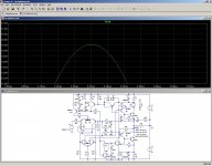
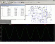
Here is what it gives in the case of the Circlophone: a small amplitude perturbating voltage is injected along with the regular audio signal.
The frequency is 10KHz to differentiate it from the noble signal, and the amplitude is 200mV peak to peak.
The behavior is also looked at with a Bode analysis.
One rail (the "clean one") for reference, then the other.
The upper rail is clearly "less clean": it is first order against second order of rejection, but it remains at ~60 dB for the audio band. Perfectible, but certainly not bad.
In the case of the Circlophone, the schottky diode's only role is energetic: they keep the ohmic losses at a minimum, while allowing the sense circuitry to operate at low currents without accuracy or matching issues.
I encourage you to discuss this kind of test on your SRJLH thread, since the Circlophone one is already overloaded with distractions of all sorts.
Attachments
Last edited:
The bottom line is: no change in the control loop has to require a corrective action from the noble loop.
I accept your sim as reasonable proof. Nothing wrong to be fixed here...
Nonetheless, moving the emitter of Q2 to the upper rail in your most
recent simulation, does it make even a tiny improvement in rejection?
Last edited:
In the case of the Circlophone, the schottky diode's only role is energetic: they keep the ohmic losses at a minimum, while allowing the sense circuitry to operate at low currents without accuracy or matching issues.
My Schottkys are biased partially on for square law Class A (Schottky
non-deterministic quiescent, you are welcome to scoff). And yours are
fully off (resistor-deterministic class A with Schottky bypass at higher
currents). I get that they are quite different, and I get why.
I've also shown this choice of class is not unique to the Circlophone's
outside sensing, Taylor summed topology. But merely choice of diode
and resistor values applicable to any quadrature feedback scheme.
I can just as easily do determinism with inside sensing, if I wanted.
You could just as easily do non-determinism with outside sensing.
If we both chose linear class A, hiding of the diodes would be moot.
I hope our useful rivalry was not just about choice of output class?
My point is that your design might be better. Because a noble loop
is less affected by any choice of outside sensing non-linearity than
when those diodes appear inside. That said, I am not yet ready to
concede defeat for the insider scheme. And I could use your help.
Member
Joined 2009
Paid Member
I wonder about the most sturdy and also conveniently pre-insulated output devices that are also available and also conducive to excellent results. I don't really require 180w to 4R. The actual requirement is a high quality, extremely sturdy, baseline example to work with. Therefore, your estimate is far more appropriate than my guess. Just bear in mind that although the design is yours, it is also true that the little volume knob and huge double-woofer speaker is mine.180W will require extremely hefty OP transistors. The Circlophone is optimally suited to a single pair of output devices, and putting out 180W on a single pair is at the very limit of what can be reliably achieved using relatively normal transistors. Paralleling is certainly not impossible, but it will require balancing resistors, and the result will be rather messy.
")
The power thing is. . . although casting a sound field both wide and deep from a single speaker is both fantastic and rare, well it is also a bit difficult to replace a triple channel amplifier's prodigious output by using a single unit instead. Let's just up and do that?
Again, thank you for the inspirations.
Thank you.You have to read builder notes from Elvee on post #56. There are lots of good info in whole thread if you can find any opportunity for reading.
I have been reading for clues and taking notes, and will do so several times more, also comparing with datasheets, also carefully comparing to posted favorable results that mention parts. I'm not good at this, but am trying hard.
I would love to see a sort of shopping list with like "first choice first" in the format "THIS, or this, or this, or this" so as to help availability and shopping. From reading your posts, it seems that you and I have the same desires for output from an amplifier. I am especially concentrating on "wide cast sound field" as from individual speakers, since that feature is so rare, albeit symmetry types and gain comp types are more prone to it.
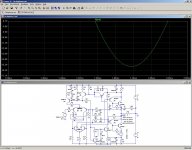
Elvee, I'm curious, does the Circlophone run out of useful headroom if the supply rails are halved - such as using a single rail +25V and 0V ?
(p.s. I recognize that an output cap would be needed)
No, not really: here is how it behaves with a total supply of 12V. It is in +/-6V, I didn't bother to make the conversion to a single supply, but it would be a mere formality.
You can see that it not only functions, but it retains all of its performances and doesn't run out of headroom.
Of course, it's only a sim, but I am pretty confident it would work identically in reality: I made tests a low voltages (not that low though), and it worked perfectly.
The only adaptations that were made were the value of R21, to keep the ~1.5mA bias, and the removal of the zeners and R26.
Attachments
In regards to ♫♪discussion about 4 ohm speakers and power over 100w♫♪ I found two of the big MJL21194 on sale. Is it suitable? If so, I was wondering what transformer to use? A 30+30vac or a 32+32vac?
Member
Joined 2009
Paid Member
I made tests a low voltages (not that low though), and it worked perfectly.
Thanks Elvee!
Member
Joined 2009
Paid Member
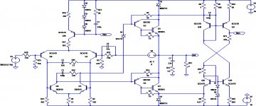
I was thinking about this amplifier and how it works. I found it easier to think of the current detection part of the circuit like current mirrors and so I joined the list of people who tried to re-draw it to suit their way of thinking. I've attached my results.
I've never seen this method for measuring the idle current and wonder if it could not be employed into other designs to achieve useful results - perhaps perfect Class AB bias control.
I've never seen this method for measuring the idle current and wonder if it could not be employed into other designs to achieve useful results - perhaps perfect Class AB bias control.
Attachments
The MJL21194 is suitable for 100W/4Ω.In regards to ♫♪discussion about 4 ohm speakers and power over 100w♫♪ I found two of the big MJL21194 on sale. Is it suitable? If so, I was wondering what transformer to use? A 30+30vac or a 32+32vac?
In principle, a 25V+25V transformer would be just sufficient for that power, so with 30V you will have plenty of margin.
In fact, with 30V, you will get ~150W, rather safely since the MJL's SOA allows for it.
I was thinking about this amplifier and how it works. I found it easier to think of the current detection part of the circuit like current mirrors and so I joined the list of people who tried to re-draw it to suit their way of thinking. .
 I have to admit it is very sleek and elegant.
It certainly could, but there are requirements that the "circlo" topology addresses easily and inherently:I've never seen this method for measuring the idle current and wonder if it could not be employed into other designs to achieve useful results - perhaps perfect Class AB bias control
- You have to locate the sensing resistors at places where they do not interfere with the output impedance or the functionning of the amplifier, especially if they are shunted by diodes.
In a classic complementary PP, this condition is easily satisfied by placing them in series with the collectors of the OP devices. - You have to inject the common-mode correction signal (the "vertical" signal) at a place where it doesn't interfere at all with the noble, differential signal (the "horizontal" signal) = perfect quadrature.
That is much trickier when you use a vertical symetry, as opposed to a lateral one, as in the Circlophone (same sex transistors).
It also has a side benefit: it can very easily encompass the totality of the amplifier, from the input LTP: this means that the output drive is not limited by the class A conditions of the small signal stages: normally, both LTP's operate in pure class A at a fixed level, but should the OP stage be starved because of a very difficult load for example, the servo will raise the operating points to whatever level is needed to remain in non-switching class B.
This is the key to the Circlophone's remarkable healthiness.
Note that the vertical loop could be more limited: stephTSF has suggested that only the phase splitter and OP stage should be included in the loop.
That is a viable option, and it has the advantage of eliminating the parasitic input current modulation, but it is less powerful than the solution I finally adopted for the Circlophone.
It would be difficult to attain such a level of flexibilty with a more conventional, vertical symetry amplifier without adding complexity.
The simple things baffle me most.
Why R8 is half the value of R6?
I'm sure those values are right,
just can't form a clear idea why...
The value of R8 is not the result of some erudite calculations, it is rather empirical.
The heart of the servo is the summation process occuring at the base of Q9 (in Bigun schematic).
The current information from the positive and negative sides of the PP are ANDed there in an analogue fashion.
Ideally, one would need two transistors connected like Q10, and the sensing resistors could be equal.
There is just one problem: R8 sits at the negative rail. Thus, one would need to transfer the information to the positive rail, without error or offset or temperature sensitivity.
This is quite possible of course, using a properly scaled current mirror + resistor + buffer.
As I wanted to keep things as simple as possible, I decided to cut some corners, and instead of making a true linear translation, plus proper ANDing, I directly added the current of Q13 to the base of Q9, and I tuned the values of R8, R9 and R10 to achieve a near perfect fit in slope and offset, so that there is a smooth and seamless transition between the two halves of the PP.
That's the result of trials and errors, and the values are not cast in bronze: it is probably possible to find even better tradeoffs.
One could also implement the whole thing properly, without shortcuts, but it doesn't seem necessary: it works well enough like that.
Last edited:
- Home
- Amplifiers
- Solid State
- ♫♪ My little cheap Circlophone© ♫♪