Member
Joined 2009
Paid Member
Big, check if you mighta goofed something? I see Q12 turning off.
Did your change to 36V rails alter this transistor's behavior?
To be honest I don't remember why I used these rails but it should work as advertised - I started with the original design and simply moved the parts around. If there's an error I don't know where it is.
Big, check if you mighta goofed something? I see Q12 turning off.
Did your change to 36V rails alter this transistor's behavior?
No, that is normal: at high currents through R8/D2, the clipping diodes D7 and D8 come into play and shunt the bias current away from Q12.
The MJL21194 is suitable for 100W/4Ω.
In principle, a 25V+25V transformer would be just sufficient for that power, so with 30V you will have plenty of margin.
In fact, with 30V, you will get ~150W, rather safely since the MJL's SOA allows for it.
Thank you!
And just to double-check for the 150w Circlophone monobloc:
Q1 BC556B
(Q2/Q7) BC556B
(Q3/Q4) BC556B, high Hfe type "B" or "C"
(Q5/Q6) BF819--in the mail, actually royal mail
(Q8/Q10) MJL21194--in the mail
(Q9/Q11) TBD--closely match Philips BD140 except more sturdy
(Q12/Q13) SC1845--in the mail
Questions:
1). Driver, big, fast, promotes euphonic, and durable?
2). Jfet input so I don't need a buffer?
3). Is D1+D2+D3 replaceable with 1/2w rated 2v@1/4w Amber LED?
4). Tom reminded me that it is a role of current with 4 ohm speakers, else there's nothing left of the 150w to actually power speakers. For usable power, it needs "filling twice the tank at double speed." How about a extremely rapid charge high capacitance dual supply that is almost a baby arc welder and with 5+ ampere (per each amplifier channel) 28+28vac transformer rated 115v, actually run on 120v, resulting in 43+43vdc rails? Is that what I need?
Driver has to be sufficient, but not oversized, it is counterproductive.Questions:
1). Driver, big, fast, promotes euphonic, and durable?
Many types have been tested/suggested.
The BD140 is OK with the MJL's, but if you want something more "comfortable", you can use the 2SA968, 2SB649 (tested), MJE172, MJE254, BD792 (not tested, but suitable).
The MJE15031 has also been tested, it is oversized but it works too.
? I don't see any jFET there2). Jfet input so I don't need a buffer?
Why would you want to do that? The Vf, capacitance, dynamic behavior, etc are not specified unlike the 1N4148, which is dirt cheap anyway.3). Is D1+D2+D3 replaceable with 1/2w rated 2v@1/4w Amber LED?
......??4). Tom reminded me that it is a role of current with 4 ohm speakers, else there's nothing left of the 150w to actually power speakers. For usable power, it needs "filling twice the tank at double speed." How about a extremely rapid charge high capacitance dual supply that is almost a baby arc welder and with 5+ ampere (per each amplifier channel) 28+28vac transformer rated 115v, actually run on 120v, resulting in 43+43vdc rails? Is that what I need?
Matched Philips BC556B--in the mail
2SB649--in the mail
So far, Circlophone 150w parts list is easy except for the BF819, which is new old stock, expensive and hard to find.
I hope that the parts I chose are optimal. It was really somewhat of a guess to figure that out, since there were so many options.
For example, a quote from Antek: ". . .specially designed to work on all standard 115V. . . " Special, yes. Standard, no. For example AS-3428 115v primary, 300va, 28+28vac choice actually results in 43+43vdc rails. My actual question was, is that DC rail voltage correct for my application?
2SB649--in the mail
So far, Circlophone 150w parts list is easy except for the BF819, which is new old stock, expensive and hard to find.
I hope that the parts I chose are optimal. It was really somewhat of a guess to figure that out, since there were so many options.
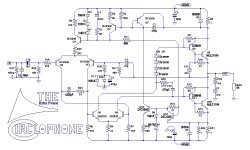
♫♪My Really Posh Circlophone© ♫♪ There is some discussion of a jfet as an upgrade.? I don't see any jFET there
Led makes extremely quiet voltage drop. It is popular in audio amplifiers because of slightly lower noise (no little power diode buzz). Actually the expected standard part is a little red 5mm from Fairchild Semiconductor. That is common, inexpensive and quiet. But I don't have them. I do have a similar 2v for use at 12.6ma (derated value) and less and I also have a stronger model 2v for use at 63ma (derated value) and less. Others could be ordered. They are not expensive.Why would you want to do that? The Vf, capacitance, dynamic behavior, etc are not specified unlike the 1N4148, which is dirt cheap anyway.
We are frequently seeing transformer primary datasheet specified for voltages that don't come out of the wall outlet. For example typical transformers include 110v primary and 115v primary, yet the typical outlet provides 120v, for example: 110v rated primary causes unexpected transformer secondary output voltage......??
For example, a quote from Antek: ". . .specially designed to work on all standard 115V. . . " Special, yes. Standard, no. For example AS-3428 115v primary, 300va, 28+28vac choice actually results in 43+43vdc rails. My actual question was, is that DC rail voltage correct for my application?
Many subs are possible: in TO39, the 2N1893 is perfect, and not difficult to source.So far, Circlophone 150w parts list is easy except for the BF819, which is new old stock, expensive and hard to find.
2SC1819 and 2SC2231 are OK too (as are KSC... obviously), and many other types: basically you want a device of >100V, >1W, with an Ft in the 50 to 150MHz range, and a Cob comprised between 5 and 15pF.
That variation is under Piersma's sole responsability, and as far as I know, it exists only on paper.♫♪My Really Posh Circlophone© ♫♪ There is some discussion of a jfet as an upgrade.
The diodes are used as clippers, not regulators, and LEDs generally have large reverse and diffusion capacitances, poor dynamic behavior, and a light-dependent reverse current, all things undesirable here.Led makes extremely quiet voltage drop. It is popular in audio amplifiers because of slightly lower noise (no little power diode buzz). Actually the expected standard part is a little red 5mm from Fairchild Semiconductor. That is common, inexpensive and quiet. But I don't have them. I do have a similar 2v for use at 12.6ma (derated value) and less and I also have a stronger model 2v for use at 63ma (derated value) and less. Others could be ordered. They are not expensive.
Knowing that the Circlophone swings to <2V of the supply rails, the calculation is easy: with 43V DC f.e., you get 41V^ on the load, that's 29V rms , and 29²/4 is 210W Pav.We are frequently seeing transformer primary datasheet specified for voltages that don't come out of the wall outlet. For example typical transformers include 110v primary and 115v primary, yet the typical outlet provides 120v, for example: 110v rated primary causes unexpected transformer secondary output voltage
For example, a quote from Antek: ". . .specially designed to work on all standard 115V. . . " Special, yes. Standard, no. For example AS-3428 115v primary, 300va, 28+28vac choice actually results in 43+43vdc rails. My actual question was, is that DC rail voltage correct for my application?
That's becoming hot for your transistors....
For the DC voltage calculation, you have to take the ripple into account, of course.
There seems to be a problem or two?The MJL21194 is suitable for 100W/4Ω.
In principle, a 25V+25V transformer would be just sufficient for that power, so with 30V you will have plenty of margin. In fact, with 30V, you will get ~150W, rather safely since the MJL's SOA allows for it.
Fail1: 30+30vac--do not want current dumper power supply. A lossy patch for lack of parallel output devices is also the weakest option for 4 ohm speakers.
Fail2: 25+25vac--do not want to weaken my expensive little Circlophone down to the power range of chips. From discrete, I want something chips don't do.
Risky Fix: End result from problem dodging = 28+28vac transformer, which is a compromise that I hope does not explode.
Two seconds of audio from 1984, most efficiently sums up this entire question: In regards to current output?
Knowing that the Circlophone swings to <2V of the supply rails, the calculation is easy: with 43V DC f.e., you get 41V^ on the load, that's 29V rms , and 29²/4 is 210W Pav.
That's becoming hot for your transistors....
Did we hit the make-break where paralleled output devices are required to complete the application? Or do I simply need a nice thick transmitter heatsink?
I'm stuck between a rock and a soft place with a huge MJL21194 output device as ironic as an endowed centurion. Help!!!
Last edited:
Handmade TO39 heatsink = really easy and free. ")
I could try the 2n3019 (a 5w driver?) with the following handmade heatsink:
None of the below soldering involves heating the transistor.
1). It looks possible to create a significant heatsink with 3 bits of ordinary 16ga copper wire (each has a TO39 size loop in the middle) stacked up with all 6 pins all evenly spaced, soldered together, 6 aluminum fins cut from the free material on bottom of the beer can added to the 6 copper pins then, lastly the new heatsink set over the TO39 with adhesive thermal compound such as JB or vid glue. That construction may be easier with 4 pins and fins.
2). Alternative construction: TO39 size circlip formations (former = drill bit) stacked up the height of the transistor, radials attached to them and then (lastly) glued onto the transistor with a thermal adhesive. Wow that's easy!
So the free heatsink is doable.
Am I in trouble over the 80v spec?
Many subs are possible: in TO39, the 2N1893 is perfect, and not difficult to source.
2SC1819 and 2SC2231 are OK too (as are KSC... obviously), and many other types: basically you want a device of >100V, >1W, with an Ft in the 50 to 150MHz range, and a Cob comprised between 5 and 15pF.
I could try the 2n3019 (a 5w driver?) with the following handmade heatsink:
None of the below soldering involves heating the transistor.
1). It looks possible to create a significant heatsink with 3 bits of ordinary 16ga copper wire (each has a TO39 size loop in the middle) stacked up with all 6 pins all evenly spaced, soldered together, 6 aluminum fins cut from the free material on bottom of the beer can added to the 6 copper pins then, lastly the new heatsink set over the TO39 with adhesive thermal compound such as JB or vid glue. That construction may be easier with 4 pins and fins.
2). Alternative construction: TO39 size circlip formations (former = drill bit) stacked up the height of the transistor, radials attached to them and then (lastly) glued onto the transistor with a thermal adhesive. Wow that's easy!
So the free heatsink is doable.
Am I in trouble over the 80v spec?
Last edited:
The datasheet says: "Wide ASO because of on chip ballast resistance."I like Sanyo devices. My current setup is using 2sd1047c. . .
Does this mean lossy output device can use either no or extremely small ballast resistors for paralleling?
If you want to squeeze the last watt from your transistors, that's your choice, your problem.There seems to be a problem or two?
Fail1: 30+30vac--do not want current dumper power supply. A lossy patch for lack of parallel output devices is also the weakest option for 4 ohm speakers.
Fail2: 25+25vac--do not want to weaken my expensive little Circlophone down to the power range of chips. From discrete, I want something chips don't do.
Risky Fix: End result from problem dodging = 28+28vac transformer, which is a compromise that I hope does not explode.
Two seconds of audio from 1984, most efficiently sums up this entire question: In regards to current output?
Did we hit the make-break where paralleled output devices are required to complete the application? Or do I simply need a nice thick transmitter heatsink?
I'm stuck between a rock and a soft place with a huge MJL21194 output device as ironic as an endowed centurion. Help!!!
100W on the MJL's is possible and conservative.
150W remains possible, but is trickier.
Going further would be unreasonable.
Anyway, the subjective difference between an amp designed for 100W with comfortable margins and one designed very tightly for 150W will be negligible.
With 25V AC nominal (supposing the transformer gives exactly that voltage at its nominal load), you have 35.4V^, minus one diode drop, 34.4V.
With 10% ripple, the minimum is at 31V, translating into a peak output of 29V, that is 20.5Vrms or 105W output power.
The actual power you will get will be somewhat different, higher or lower, depending on the characteristics of your transformer, mainly. It could be 10% higher or lower, and the actual power will also depend on the mains voltage, the temperature of the windings, etc, but as I said, that makes very little subjective difference.
If the total supply voltage remains under 80V, the 2N3019 is fine. That is the case with a 25V transformer (~=70V total).I could try the 2n3019 (a 5w driver?) with the following handmade heatsink:
None of the below soldering involves heating the transistor.
1). It looks possible to create a significant heatsink with 3 bits of ordinary 16ga copper wire (each has a TO39 size loop in the middle) stacked up with all 6 pins all evenly spaced, soldered together, 6 aluminum fins cut from the free material on bottom of the beer can added to the 6 copper pins then, lastly the new heatsink set over the TO39 with adhesive thermal compound such as JB or vid glue. That construction may be easier with 4 pins and fins.
2). Alternative construction: TO39 size circlip formations (former = drill bit) stacked up the height of the transistor, radials attached to them and then (lastly) glued onto the transistor with a thermal adhesive. Wow that's easy!
So the free heatsink is doable.
Am I in trouble over the 80v spec?
You don't need to craft your own sink, there is plenty of choice available:
To 5 Heatsink
AAVID THERMALLOY|5F-2|HEAT SINK, TO-5, 62°C/W | Farnell United Kingdom
Heatsinks - Main Page
etc..
If you want to make your own, you can use a small length of 1/4" copper tube that you cut open. You can leave it cylindrical or spread the top.
Anyway, a heatsink is not technically needed for supply voltages of up to ~40V.
The case will become uncomfortably hot, but it will work without problems.
You can do your first tests without, order a pair at your leisure and fit them later.
The datasheet says: "Wide ASO because of on chip ballast resistance."
Does this mean lossy output device can use either no or extremely small ballast resistors for paralleling?
I don't know what does it mean exactly. If there is a emitter resistor inside chip which recovers some drawback of transistor, it shouldn't be a good thing. At least we know that Circlophone doesn't use emitter resistors at output.
Scale R26 for the new voltage drop?
Though I don't foresee Q1 exploding if you left it 2K2...
Q6 might be nearing its 80VCEO limit on the upswing.
Since this is always on, and base has pull down resistor,
the base here definately isn't "open" , I don't know if
VCEO limit matters? VCBO is 140V according to ST...
Though I don't foresee Q1 exploding if you left it 2K2...
Q6 might be nearing its 80VCEO limit on the upswing.
Since this is always on, and base has pull down resistor,
the base here definately isn't "open" , I don't know if
VCEO limit matters? VCBO is 140V according to ST...
Last edited:
Thank you very much!
I got this far (photo). Do you see any problems?
Some remarks:
I would leave C5 on the right of R19: that's the normal RFI/band-limiting-filter configuration.
By placing it on the left, R19 becomes a base stopper. This could be justified, but only under very extreme and special circumstances, like Terranigma's.
It is preferable to leave C6 at 1.5nF.
1.2nF won't cause problems, but the optimum is at or near 1.5nF.
R26 has no active role, just damping and path-breaking. It could be reduced or omitted without problems, but should not be increased, as it will create supplementary poles with parasitic capacitances.
As Ken said, the 2N3019 are a bit on the edge for 84V, at least theoretically. I don't foresee any problem, but if you can sub them with 2N1893, that would be completely orthodox.
The 2SC5171 should work, the Cob is marginally high, but nothing alarming.
The 2SC2073 is completely unsuitable.
If you prefer, you can use a single 43V/1.3W zener, or two of 20V and 22V 400mW, the exact voltage is not critical anyway.
With the MJL's, C11 should not be implemented.
If you have the choice, use SR502 schottky's instead of SR506, they have a slightly lower drop.
I just realized that the 2SA1209 only has a 140mA Ic rating, so it's out.Thank you.
For subbing 2n3019 what about just using the complimentary partner to the driver, for easier shopping?
if q9/q11=2sa1209 then q5/q6=2sc2911?
or
if q9/q11=2SB649 then q5/q6=2sd669?
Or do I just need to stick with 2N1893?
The 2SD669 is OK as phase splitter
I'm currently working to "modernproof" D7 to avoid "reproductions" with inaccurate datasheets.
For these four, the datasheets should be reasonably accurate.
Are any of these high availability parts suitable for D7?
1n5819 40v
1n5822 40v
1n5711 70v
1n6263 60v
It seems that D7 is the last piece of the puzzle for circa 2012 parts list.
P.S.
I have updated the "extra power" schematic with current production ST 2n1893 at Q5/16.
The attached radio does output some RF.I would leave C5 on the right of R19: that's the normal RFI/band-limiting-filter configuration. By placing it on the left, R19 becomes a base stopper. This could be justified, but only under very extreme and special circumstances, like Terranigma's.
If at the right of R19, the efficient little cap will increase amplitude of noise at pitches directly lower than the intended filtering; so, how about an RC for RF instead of just the cap?
Okay. Thanks!It is preferable to leave C6 at 1.5nF.
1.2nF won't cause problems, but the optimum is at or near 1.5nF.
Upon reading the whole thread again, it seemed that everyone had slightly more V+ than zener, so I marked down a 2 of 20v zener (40v)--The little package of a minimum purchase typically has 4 or 5 zener, so maybe it is convenient. If there is a problem, please mention it.If you prefer, you can use a single 43V/1.3W zener, or two of 20V and 22V 400mW, the exact voltage is not critical anyway.
Okay. Thanks!With the MJL's, C11 should not be implemented.
If I buy new production SR502, they will be SR506 with an SR502 paint job. That doesn't make a different part, just a less accurate datasheet. If you'd like a different part, we'd need to find it in some other IC package size, at least. I don't mind using a more expensive part as long as it is easily available, so please indicate if you want that.If you have the choice, use SR502 schottky's instead of SR506, they have a slightly lower drop.
So, for wrapping up some schematic and parts list documentation:
1). A really good performing D7 of current production and high availability?
2). Need to know if any resistors continuously pull more than 1/8w?
3). Proof the parts list and "extra power" schematic one last time.
4). Make a power supply somewhat auto adapt to speaker load
5). Find a PCB photo that is preferred/accurate?
Do you use it with a radio transmitter?The attached radio does output some RF
Why would the cap increase the amplitude?If at the right of R19, the efficient little cap will increase amplitude of noise at pitches directly lower than the intended filtering; so, how about an RC for RF instead of just the cap?
The schottky's role is minor, they simply improve the energetic efficiency and could be omitted without problem, there is no need for high performance there.If I buy new production SR502, they will be SR506 with an SR502 paint job. That doesn't make a different part, just a less accurate datasheet. If you'd like a different part, we'd need to find it in some other IC package size, at least. I don't mind using a more expensive part as long as it is easily available, so please indicate if you want that.
A reverse voltage of less than 5V is more than sufficient, but each has to carry half of the output current, which rules out the 1N5822.
The 1N5711 and 6263 are poor choices for the clipper: they are high voltage/low current, low conductance types, better stick with BAT8x types.
Many do at Vs=40V, and even the ones that don't should be oversized.2). Need to know if any resistors continuously pull more than 1/8w?
The whole circuit has been designed to use exclusively 0.25W resistors and finding the one or two exceptions makes little sense.
I do not see how this could be implemented without huge complications.4). Make a power supply somewhat auto adapt to speaker load
- Home
- Amplifiers
- Solid State
- ♫♪ My little cheap Circlophone© ♫♪