With your supply, transistors, and on a 4 ohm load, you run no risk of exploding your OP devices. If you try to abuse it, you will probably damage your speaker, but not the amplifier. I recommend you first try to build the naked Circlophone, and you add your bells and whistles later (and incrementally), when you're satisfied everything works fine. Otherwise, there is a risk all ends in a big mess for unclear reasons.
Yes, I'm starting it off easily with a "core" amplifier.
The only mess that occurred was I was overly enthusiastic with transistor shopping and bought too many.
") The transistors have been arriving slowly.
The transistors have been arriving slowly.Transistor matching. . . for the first time. Wow, this is easy!
Kec 2sa968a hfe=216.4, hfe=217 Is "K" a good brand?
Motorola 2n3019 hfe=121 (span of 10 units was 88 to 151 hfe, avg 121)
ST 2N1893 hfe=95 (span of 10 units was 90 to 95 hfe, avg 93.5)
While I'm awaiting for a opportunity for build second @wakibaki pcb, my first build blown up after longish listening sessions due to not using thermal paste at my outputs (Moto MJ15003s). Because I couldn't stop listening even with that crappy test setup. After disaster, I decided to take a chance with @powerflux pcb. But in doubt of what to do now. I recently bought 50 pieces of genuine Philips BC560C's with very close 520-540 hfe. I really want to build something for real with these.
As my purpose for choosing this particular amplifier, I'll be discovering how you and odysseybmx414 and Elvee achieved the published sound quality. Since you're in doubt of what to do, may I suggest that you re-create/repair your original work to use for a baseline?
As for non-audio workload (RF), instead of using the fastest parts you can find, perhaps you might like slower parts less suited to RF amplifiers? You might also consider a picofareds cap shunting across the +and-inputs documented in the balanced input post. Non-audio workload and accidental conductivity are likely causes of failure for MJ15003. Tom and Pacific could give you better details and better explanations than I could for "Radio Production Environment" filtering, turning off the amplification of RF, and filtering your transformer windings as well.
So, I'm guess that I'm thinking of repairing your original build and then adding high quality filtering.
Since you're in doubt of what to do, may I suggest that you re-create/repair your original work to use for a baseline.
My purpose with that comment was rebuild Circlophone but which version.. Modify wakibaki? New pcb with mix of both? More trial with powerflux?
I actually did everything for match same silence performance with new pcb but failed everytime. I tried same type small transistors, drivers, output trannies, same type capacitors, resistors on new pcb. In terms of sound quality, nothing wrong with new pcb but I can't help myself for figure out why wakibaki's not influenced by my ambient noise. This is very specific issue related with me. That's all.
I tried repair old pcb, but couldn't figure out why it didn't work again. After spending too much time then I decided try new one..
I have to modify wakibaki's neat pads before etching it again.
Last edited:
Daniel...I built a similar Circlophone to the one you plan to.
Mine runs on (has been for a few months, I think) +-40V rails, adequate heatsink+fan cooling. . . .
I used the wakabaki PCB. The only issue it has is an extremely minor one, not even an issue at all in my opinion. One of the capacitors on the board (they are all 3 pads to allow use for small or large ones) is missing a connection between two of its pads, the one designating the smaller capacitor option is connected while the one designating the larger option is not. . .
I monitored the unit on a scope through a few conditions and did not see any hint of an issue. I did not drive it with a square wave into a capacitive load however, but I have been using it extensively for a bit of time now. . . .
Thank you very much! I found the PCB to use for a guideline. I don't know why the NFB cap isn't set over by the input cap with the protection diodes trackside if space saving is wanted and, of course signal star ground conveniently all in one place, but other than that, it looks good.
You have fan cooling? Well, I'm curious about the operating temperature. Did you scope the power?
Well, possibly the convenient output section from the powerflux made as a module, and then use the wakibai for the rest?My purpose with that comment was rebuild Circlophone but which version.. Modify wakibaki? New pcb with mix of both? More trial with powerflux?
Well, possibly the convenient output section from the powerflux made as a module, and then use the wakibai for the rest?
Good idea, but it is not going to be easy while using vector based graph editor (inkscape) rather than sophisticated pcb editing tools.
I just received some news from Mickeymoose
He will soon offer his version of the Circlophone, the luxury edition: professional quality PCB, integral fan + controller, balanced input, VUmeter, etc.
(some pics of the beta version can be seen here and here )
He has also offered to provide the metalwork, either ready-to-use (pre-drilled, etc) or DIY.
What are your preferences? Give your opinion.
http://www.ti.com/lit/an/sloa054d/sloa054d.pdf
Fully differential paper seems somewhat relevant, maybe useful?
Though we have both explored fully differential current outputs
rather than voltage... Does that make what we have done to be
discrete operational transconductance amplifiers instead?
Fully differential paper seems somewhat relevant, maybe useful?
Though we have both explored fully differential current outputs
rather than voltage... Does that make what we have done to be
discrete operational transconductance amplifiers instead?
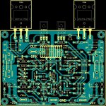
..... PCB was layout in few hours ,just to improuve, my skill and have, a new PCB in my collection
Regards Alex.
Hi Alex,
Nice to see another one of your very nice PCB´s ;-)
Karsten
Yes, very nice work indeed. Even if I spent more than a few days on it, I couldn't match that...... PCB was layout in few hours ,just to improuve, my skill and have, a new PCB in my collection
Regards Alex.
That's exactly what a forum is about: everyone contributes to the best of his abilities, and the final result is awesome.
Differential topologies do have clear advantages: cancellation of some types of nasties, etc.http://www.ti.com/lit/an/sloa054d/sloa054d.pdf
Fully differential paper seems somewhat relevant, maybe useful?
Though we have both explored fully differential current outputs
rather than voltage... Does that make what we have done to be
discrete operational transconductance amplifiers instead?
But they generally have the drawback of doubling the BOM (at least for the critical output parts).
That's why I mostly disregarded them, but I have to admit I happened to indulge in some wild fantasies (in class A as if this was not enough).
I might publish them, if I am able to get past my inhibitions....
Transconductance amplifiers do not normally belong to the category of "quadrature" amplifiers: they are regular class B amps, but with a current output instead of voltage.
 ?
?Transconductance amplifiers do not normally belong to the category of "quadrature" amplifiers: they are regular class B amps, but with a current output instead of voltage.
Yeah, but put your style of sensing between an OTA and rails,
and feed back to Iabc. I think you might have a circlophone?
An actual circlophone, though with chip limited dissipation.
Maybe enough for a headphone or something?
My point was really that FDA's and OTAs have a common mode
input that could be abused for some quadrature fun and games.
FDAs output voltages, and center upon a common mode voltage.
OTAs output a current, and center upon a common mode current.
Same exact things, except completely different.
It would be helpful if an OTA fully brought out the two currents
as differential drives, rather than collide them inside the chip.
Maybe some existing OTA already has a differential current
output configuration suitable to drive something external?
If such a chip exists, I am unaware of it, but searching...
Maybe this is doable with a conventional OTA as a CFP?
By abusing the currents to either rail as-if they were drives...
You are using class B, current sensing, and the threshold of
a logic based rule to nudge the bias up to ideal AB + CCS.
I am using enriched class A, current sensing, and threshold
of a curved sum rule to nudge the bias down to AB + CCS
(very non-ideal AB+CCS rule, but also very low part count).
Same exact things, except completely different.
Once you breach the OTA chip no-no, might as well bust
out with LM3Whatever output devices. I know you gone
there before too, so no playing innocent...
Last edited:
Excellent looking 30 watt amp...... PCB was layout in few hours ,just to improve, my skill and have, a new PCB in my collection
Regards Alex.
Here's a few notes for wider range:
D4/D5 MBR745, a TO220 size part (a "solar" shottky de-rated barely)
D8,D9 11N4744 (some 1w zener de-rated slightly) (~32+32vdc rails)
D7 one of these: BAT83, BAT86, BAT82 (make the label say "BAT8X")
Q12,Q13 one of these: 2SC1845, 2SC2240, 2N5551 (voltage tolerance up)
Q9/Q11 2SB649 (better than fake BD140 and easier to find than real NOS 8w Philips BD140)
D1,D2,D3,D6,D10,D11 = 1n914 (higher availability than 1n1418)
Possibly R17=12k (gain up in proportion to potential up)
C12=330pF (average value of real usage examples)
R21=47k (~32+32vdc rails)
other notes:
The current seen by R8, R11, R24 is low because of the paralleled heavy duty schottky diode.
Consider relocating fuses to mains side of transformer so as to avoid catastrophic offset fire hazard.
You can mark D7 as "BAT8X" because of the difficult availability of BAT type diodes.
If ~32+32vdc rails, D8,D9=1N4744 and R21=47k (50 watt to 8R, 100w to 4R)
If ~37+37vdc rails, D8,D9=1n4746 and R21=56k (70 watt to 8R, 140w to 4R)
So, instead of a 30w amp, there's a 70w amp.
- Home
- Amplifiers
- Solid State
- ♫♪ My little cheap Circlophone© ♫♪