The major feedback loop has no impact, at least to a first order, on the output impedance of the TIS. You can confirm this by disabling the major loop by means of a large capacitor shunting the inverting input of the amplifier to ground or using a large inductor in series with the inverting input of the amplifier.
I did, and again got a different result.
Attachments
The major feedback loop has no impact, at least to a first order, on the output impedance of the TIS. You can confirm this by disabling the major loop by means of a large capacitor shunting the inverting input of the amplifier to ground or using a large inductor in series with the inverting input of the amplifier.
Further, Bob, I have also demonstrated that the minor loop has no effect on the loop gain of the ANF current source. Why do you find this so difficult to appreciate?
Tomorrow I'll do as you've asked; viz. run a sim of the loop gain of the current source with a resistive load.

Thanks, Mike. I'll look forward to your result.
Did you disable both loops?
Cheers,
Bob
Can you refer me to where Stochino and Self discussed this (I did not see any reference to this in Self's 5th edition).
Self 5th Edition pp 94 - 95.
I'm very interested in learning more about any disadvantages in the replica cascode driving technique as compared to the other technique.
Hope this helps until Manso's time zone is awake.
Best wishes
David
Why even simulate the current source with all the other amplifier guff if you're going to isolate it? Why not just simulate it by itself? And in order to show off the "intrinsic" behaviour, surely it would be best to present it with the "kindest" load, which for a current source is a short circuit from DC to daylight (the dual of the "kindest" load for a voltage source being an open circuit from DC to daylight).
Harry, you're a genius!
 Of course in order to obviate the load on a voltage source its output must be open circuit. Conversely, in order to eliminate the load on a nominal current source its output must be short circuit. Why I didn't remember this most elementary facet of electrical circuit theory I haven't the faintest idea!
Now, using a large inductor in series with the current source output does isolate it from the rest of the circuit, but puts maximum loading on the current source because its output is then a virtual open circuit at the frequencies of interest. This is the exact opposite of what is required to establish the intrinsic loop transmission of the current source, and explains the relatively low loop gain I obtained with the inductor in situ.
Therefore, what is required in principal is a large capacitor shunting the output of the current source to ground. I have tried this, and, although loop transmission increases from roughly 12dB with the series inductor to 59dB across the audio band with the shunt capacitor, there is virtually no difference in loop gain with and without the shunt capacitor. I am yet to identify a reason for this behaviour. Any ideas anyone?
Nevertheless, Harry, you're right in suggesting that extraneous circuitry need not be included to establish the intrinsic loop gain of the ANF current source, unless it is desired to quantify the effect of such circuitry on the loop gain, which, as I have indicated above, is negligible at least in the case of the amplifier topology at issue.
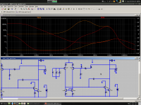
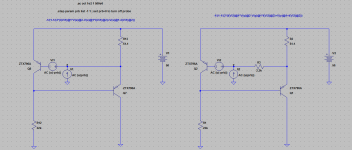
The figure below shows the loop gain of the amplified negative feedback current source in isolation with its output short circuited to ground. The asc file and transistor models are also included.
Bob, I think it is now apparent why loading the current source resistively is not a good thing, so I shall not be running that simulation I promised you after all.
Attachments
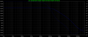
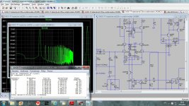
You'll recall that I indicated somewhere in this thread that placing a resistor in series with the control transistor in the amplified negative feedback (ANF) current source reduces loop gain. This remains true as shown below.
Of interest, however, inclusion of the 2K2 resistor also reduces the unity loop gain frequency drastically; in this case from 50Mhz (phase margin~44 degrees) to just under 2Mhz (phase margin~83 degrees).
Of interest, however, inclusion of the 2K2 resistor also reduces the unity loop gain frequency drastically; in this case from 50Mhz (phase margin~44 degrees) to just under 2Mhz (phase margin~83 degrees).
Attachments
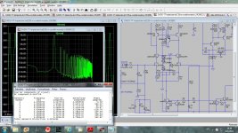
You'll recall that I indicated somewhere in this thread that placing a resistor in series with the control transistor in the amplified negative feedback (ANF) current source reduces loop gain. This remains true as shown below.
Of interest, however, inclusion of the 2K2 resistor also reduces the unity loop gain frequency drastically; in this case from 50Mhz (phase margin~44 degrees) to just under 2Mhz (phase margin~83 degrees).
Isnt that a good thing ?? Although I wouldnt make such a drastic reduction.
Isnt that a good thing ?? Although I wouldnt make such a drastic reduction.
As far as I am aware nobody has reported instability local to the ANF current source in the absence of the resistor in series with the base of the control transistor in amplifier applications.
Therefore since the 2K2 resistor reduces loop gain at 20KHz by 20dB its inclusion may not be a good thing.
Presumably this reduction in loop gain is due to the low pass filter effect that occurs with the resistor in conjuction with the input capacitance of the control transistor.
Last edited:
Hi Bob
Dave Zan beat me to it.
It will be interesting if you could confirm the same result as Self with the blameless as it might show exactly why your design overcomes this or that maybe your design will also perform better if those cascodes are biased from the LTP.
Thanks for pointing me to this, manso and Dave.
Self discusses the driven cascode and concludes that direct drive at AC from the tail works well, and he was unable to get satisfactory results from replica drive derived from the output signal. His setup was using a very high common mode voltage of 5V at an output level of 10V and a gain of 2 in a test amplifier without an output stage, but Miller compensated. He observed that CM distortion increased at high frequencies. Distortion was 2nd harmonic at 0.002% at 15kHz. He observed that the CM distortion percentage (2nd harmonic) was proportional to the square of the CM voltage (seems odd) and speculated that in an amplifier with a closed loop gain of 23 and operating at the same output level the CM distortion would be less than 0.00002%.
He observed that the distortion was worse at low Vce and speculated that the effect was either Early effect or Ccb nonlinearity, both of which can be expected to get worse at low Vce. He said that the CM distortion effect cannot be found in SPICE simulation and opined that this may be due to the linear modeling in SPICE of the Early effect. This would not account for the effect if the CM distortion was mainly from Ccb. He then noted that changing the input devices did not change the effect, so then concluded the effect is not from Early effect. But then he subsequently concluded that it was Early effect. These conclusions are a bit confusing to me when taken together.
He then bootstrapped the cascode from the LTP tail with AC coupling, placing the cascode DC bias at about half the positive rail voltage. In an arrangement with gain of 1.3 and output level of 5V, the cascode reduced CM distortion from 0.003% to 0.0015% at 20kHz and concluded that the cascode completely eliminated the HF distortion effect.
Curiously, at lower frequencies below 5kHz in this arrangement the cascode version produced 20% MORE CM distortion than the non-cascode version.
When instead he used a replica of the feedback signal whose amplitude was controlled by a variable attenuator he got only a small reduction in CM distortion, and at a drive level of only 131mV, way off from what should have been the results if the replica feed was operating as hoped. Details of the replica feed circuit or distortion plot were not shown, so it is unclear why the replica feed did not work. It was speculated that the replica feed did not work because the output signal is phase shifted compared with the input signal. However, the closed-loop phase shift of the amplifier at 20kHz should have been quite small, perhaps only 5 degrees.
Bottom line is that I should do some SPICE simulations with both types of cascode drive and see how each performs when I get some time. I should also verify whether or not SPICE is blind to this effect, as Self asserts.
Finally, in my MOSFET amplifier where replica drive of the cascode appeared to work, the differences that might account for the good performance of the replica drive could be due to the lower (normal) CM voltage level, the use of MIC compensation, or the use of JFETs in my LTP. I should note that I did not try driving the cascode bases from the LTP tail, so I cannot say that that would not have been even better.
Cheers,
Bob
I didnt quite understand the reason for the analysis in the first place is it to obtain the highest output impedance ?? This is important for CMRR and PSRR. If one wants very good performance the anf current source is the way to go; to include low noise tempco and better Zout the better option is the one shown by Cordell with the zener, the de facto CS I like too use. For better youll have to use cascoded and Self shows the improved results obtained by its use. The choice of transistors is also important if one wants high performance.
One can obtain a near 7 times better Zout with the inclusion of another active part, opamp companies seem to think its worth the complexity and use it to obtain the very high CMRR and PSRR figures they do.
One can obtain a near 7 times better Zout with the inclusion of another active part, opamp companies seem to think its worth the complexity and use it to obtain the very high CMRR and PSRR figures they do.
Bob thanks for the clarification, I did this years ago and If I remember correctly you can see the effect via simulation but to a very small degree. This ialso depends on the device models and Self may be right about the inadequite early voltage parameter.
This chapter from Self is very revealing of unsuspected distortion mechanisms which one sees many designers fail to address. It also provides good insight as to the selection of active devices to obtain optimal performance.
BTW why isnt there and when will there be a DIY board available of your amp ??
Im sure some would like to build it.
Thanks for pointing me to this, manso and Dave.
Self discusses the driven cascode and concludes that direct drive at AC from the tail works well, and he was unable to get satisfactory results from replica drive derived from the output signal. His setup was using a very high common mode voltage of 5V at an output level of 10V and a gain of 2 in a test amplifier without an output stage, but Miller compensated. He observed that CM distortion increased at high frequencies. Distortion was 2nd harmonic at 0.002% at 15kHz. He observed that the CM distortion percentage (2nd harmonic) was proportional to the square of the CM voltage (seems odd) and speculated that in an amplifier with a closed loop gain of 23 and operating at the same output level the CM distortion would be less than 0.00002%.
He observed that the distortion was worse at low Vce and speculated that the effect was either Early effect or Ccb nonlinearity, both of which can be expected to get worse at low Vce. He said that the CM distortion effect cannot be found in SPICE simulation and opined that this may be due to the linear modeling in SPICE of the Early effect. This would not account for the effect if the CM distortion was mainly from Ccb. He then noted that changing the input devices did not change the effect, so then concluded the effect is not from Early effect. But then he subsequently concluded that it was Early effect. These conclusions are a bit confusing to me when taken together.
He then bootstrapped the cascode from the LTP tail with AC coupling, placing the cascode DC bias at about half the positive rail voltage. In an arrangement with gain of 1.3 and output level of 5V, the cascode reduced CM distortion from 0.003% to 0.0015% at 20kHz and concluded that the cascode completely eliminated the HF distortion effect.
Curiously, at lower frequencies below 5kHz in this arrangement the cascode version produced 20% MORE CM distortion than the non-cascode version.
When instead he used a replica of the feedback signal whose amplitude was controlled by a variable attenuator he got only a small reduction in CM distortion, and at a drive level of only 131mV, way off from what should have been the results if the replica feed was operating as hoped. Details of the replica feed circuit or distortion plot were not shown, so it is unclear why the replica feed did not work. It was speculated that the replica feed did not work because the output signal is phase shifted compared with the input signal. However, the closed-loop phase shift of the amplifier at 20kHz should have been quite small, perhaps only 5 degrees.
Bottom line is that I should do some SPICE simulations with both types of cascode drive and see how each performs when I get some time. I should also verify whether or not SPICE is blind to this effect, as Self asserts.
Finally, in my MOSFET amplifier where replica drive of the cascode appeared to work, the differences that might account for the good performance of the replica drive could be due to the lower (normal) CM voltage level, the use of MIC compensation, or the use of JFETs in my LTP. I should note that I did not try driving the cascode bases from the LTP tail, so I cannot say that that would not have been even better.
Cheers,
Bob
Hi Bob,
I used driving the input cascode bases directly from the input tail in my TT amp http://www.diyaudio.com/forums/solid-state/182554-thermaltrak-tmc-amp-2.html#post2634734 and you suggested this to me(actually to use aditional BJT to do that, Q9 in this case).
I simulated a bootstraped input cascode and connected to the ground and difference in distortion eas huge. It could be because I used fets for the LTP not bjts.
BR Damir
Attachments
Harry, you're a genius!
Now, using a large inductor in series with the current source output does isolate it from the rest of the circuit, but puts maximum loading on the current source because its output is then a virtual open circuit at the frequencies of interest. This is the exact opposite of what is required to establish the intrinsic loop transmission of the current source, and explains the relatively low loop gain I obtained with the inductor in situ.
Therefore, what is required in principal is a large capacitor shunting the output of the current source to ground. I have tried this, and, although loop transmission increases from roughly 12dB with the series inductor to 59dB across the audio band with the shunt capacitor, there is virtually no difference in loop gain with and without the shunt capacitor. I am yet to identify a reason for this behaviour. Any ideas anyone?
Nevertheless, Harry, you're right in suggesting that extraneous circuitry need not be included to establish the intrinsic loop gain of the ANF current source, unless it is desired to quantify the effect of such circuitry on the loop gain, which, as I have indicated above, is negligible at least in the case of the amplifier topology at issue.
The figure below shows the loop gain of the amplified negative feedback current source in isolation with its output short circuited to ground. The asc file and transistor models are also included.
Bob, I think it is now apparent why loading the current source resistively is not a good thing, so I shall not be running that simulation I promised you after all.
Hi Mike,
Thanks for running these simpler simulations and arriving at the higher loop gain. It looks like we are all on basically the same page, now.
Loading the current source resistively is OK, but only if it does not allow a too-large amount of gain in the common-emitter-connected control transistor. But testing the feedback current source in isolation while it is loaded into a short is best.
With respect to the series base resistor, I think its use is a matter of degree. As you pointed out, a 2.2k value greatly reduces the loop gain to a point that it may interfere with the goodness provided by the feedback action. It does, of course, give us a more comfortable phase margin in the feedback current source loop. At the same time, zero resistance may often give a phase margin that is smaller than we'd really like.
So perhaps an intermediate value of that resistor is what would be good. Maybe a couple hundred ohms. Enough resistance to bring the ULGF of that loop to 10MHz or less is probably enough.
Cheers,
Bob
Bob thanks for the clarification, I did this years ago and If I remember correctly you can see the effect via simulation but to a very small degree. This ialso depends on the device models and Self may be right about the inadequite early voltage parameter.
This chapter from Self is very revealing of unsuspected distortion mechanisms which one sees many designers fail to address. It also provides good insight as to the selection of active devices to obtain optimal performance.
BTW why isnt there and when will there be a DIY board available of your amp ??
Im sure some would like to build it.
Hi manso,
Do you mean the 30-year-old MOSFET power amp with error correction?
If so, people have asked over the years, but I have never gotten around to it. It was only a 50W amp anyway, so I'm not sure how many would be interested in that low power level.
As an interesting aside, around 1983 I began working on a 200 watt version of it and even had a prototype working, but had to drop it as work demands became intense due to the ATT divestiture and my move from Bell Labs to Bellcore. I recall at the time I was not able to get the P and N channel Hexfets in anything larger than the TO-220 package, so making a high-power amp was painful.
Much later, of course, Halcro took that path and carried the mantle of MOSFET power amplifiers with error correction (the circuit in one of their patents looks remarkably similar).
Cheers,
Bob
With respect to the series base resistor, I think its use is a matter of degree. As you pointed out, a 2.2k value greatly reduces the loop gain to a point that it may interfere with the goodness provided by the feedback action. It does, of course, give us a more comfortable phase margin in the feedback current source loop. At the same time, zero resistance may often give a phase margin that is smaller than we'd really like.
So perhaps an intermediate value of that resistor is what would be good. Maybe a couple hundred ohms. Enough resistance to bring the ULGF of that loop to 10MHz or less is probably enough.
Hi Bob,
Have you encountered instability in an ANF current source in which the control element's resistor is excluded?
For example, I, J. L. Hood and our own Bonsai use the ANF current source in their designs without that resistor.

Last edited:
Hi Bob,
I used driving the input cascode bases directly from the input tail in my TT amp http://www.diyaudio.com/forums/solid-state/182554-thermaltrak-tmc-amp-2.html#post2634734 and you suggested this to me(actually to use aditional BJT to do that, Q9 in this case).
I simulated a bootstraped input cascode and connected to the ground and difference in distortion eas huge. It could be because I used fets for the LTP not bjts.
BR Damir
Hi dadod,
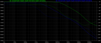
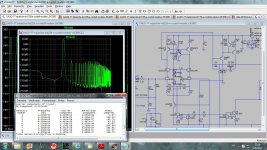
Great piece of information. So this would argue that the effect of common-mode HF distortion is indeed revealed by SPICE, if I interpret what you are saying correctly. I note that these pictures you show are for 20kHz THD.
As you point out, you are using JFETs for the LTP, not BJTs. And JFETs can be a bit more prone to CM distortion, so it is conceivable that that could account for the difference between your experience and that of Self.
BTW, it would be easy for you to complete the experiment by changing the simulation slightly to connect the cascode base driving signal to a replica of the feedback signal instead of to ground or the tail. That would answer the question, at least for the case of your amplifier, whether there is much difference in driving the cascode from the tail or a replica derived from the output.
Cheers,
Bob
Hi Bob,
Have you encountered instability in an ANF current source in which the control element's resistor is excluded?
For example, I, J. L. Hood and our own Bonsai use the ANF current source in their designs without that resistor.
Hi Mike,
I have not encountered that instability, at least as far as I know. But I also didn't know how much phase margin against instability I had
.Cheers,
Bob
shorting out CSs
Unfair
Don't I get a 'genius' moniker for pointing this out first in post #3466?Harry, you're a genius!
.... The figure below shows the loop gain of the amplified negative feedback current source in isolation with its output short circuited to ground. The asc file and transistor models are also included.
Unfair
Hi dadod,
Great piece of information. So this would argue that the effect of common-mode HF distortion is indeed revealed by SPICE, if I interpret what you are saying correctly. I note that these pictures you show are for 20kHz THD.
As you point out, you are using JFETs for the LTP, not BJTs. And JFETs can be a bit more prone to CM distortion, so it is conceivable that that could account for the difference between your experience and that of Self.
BTW, it would be easy for you to complete the experiment by changing the simulation slightly to connect the cascode base driving signal to a replica of the feedback signal instead of to ground or the tail. That would answer the question, at least for the case of your amplifier, whether there is much difference in driving the cascode from the tail or a replica derived from the output.
Cheers,
Bob
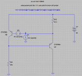
Hi Bob,
Thank you Bob, and here is next simulation were the cascode base driving signal connected to a replica of the feedback signal, with a bit worst result then if driving from the tail. Could be because the phase difference?
BR Damir
Attachments
- Home
- Amplifiers
- Solid State
- Bob Cordell's Power amplifier book