With an inductor at the collector, open-loop gain will dramatically worsen due to the output transistor's Rin=Rm.
Completely untrue.
I have no idea what you're talking about; which "base resistance" are you refering to? I cannot make head or tail at your attempt to simulate loop gain of the ANF current source.
Do you even know how to use the "Tian" lope gain probe in LTSpice? If so, why haven't you used it?
Anyway, I don't owe you an explanation for anything. I have demonstrated to my satisfaction the typical loop gain of the ANF current source. That is sufficient.
Do you even know how to use the "Tian" lope gain probe in LTSpice? If so, why haven't you used it?
Anyway, I don't owe you an explanation for anything. I have demonstrated to my satisfaction the typical loop gain of the ANF current source. That is sufficient.
Last edited:
I never said you owed me an explanation. But it would be appreciated because we can't both be right at the same time. It is strange that you would stop talking now when you are normally so eager to tell us how wrong we are.
Those were not actually attempts to simulate OLG, and because Rbe and Rm are ratios, in AC analysis it doesn't matter anyways. As long as there is a stimulating source the impedances only need to be derived from local signals.
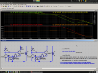
Here is the loopgain. Nothing changes.
Of course, because feedback is not taken from the output, loopgain tells us nothing but whether the circuit is stable. Notice that when simulated correctly, phase margin dips to 37 degrees.
Those were not actually attempts to simulate OLG, and because Rbe and Rm are ratios, in AC analysis it doesn't matter anyways. As long as there is a stimulating source the impedances only need to be derived from local signals.
Here is the loopgain. Nothing changes.
Of course, because feedback is not taken from the output, loopgain tells us nothing but whether the circuit is stable. Notice that when simulated correctly, phase margin dips to 37 degrees.
Attachments
.. from #3430 etc
.. from #3430
ANF_loop_gain.asc
BJT_models.txt
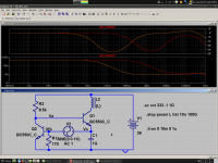
Apart from Bias Spreader, LTP CCS, Zobels & output L , this might even be a 'real life' working amp.
Michael, can we take this as an example of your views on good practice and your target level of THD/stability? leaving out your L1 of course
___________
If you want the Loop Gain of the CCS in situ with the effects of OPS, Ccb etc, remove the inductor.
If you want to measure its output Z, then use your inductor and connect the other end to earth.
If you want to know the relative effect of OPS on VAS & VAS on OPS, use your inductor and measure Z on either side of the inductor. I do this in #2877 http://www.diyaudio.com/forums/solid-state/171159-bob-cordells-power-amplifier-book-288.html#post3475959
The description of an Inductor as a current source was used by many basic electronic texts in da old days to describe the evolution of simple amplifiers from a single BJT with collector resistor ... to full Class B with LTP i/p .. sorta the Jurassic prelude to Bob's Fig 3.1
It is also the basis of many Golden Pinnae SE amps bla bla.
___________
But why are we discussing this? I think MikeK's analysis is flawed ... but so what? Is this helping us design better amps or understand them better?
[deleted : 104 pg rant about how I analysed all this in my 1000 pg unpublished book on how to grow Cox's Orange Pippins in Antartica ]
.. from #3430
ANF_loop_gain.asc
BJT_models.txt
Apart from Bias Spreader, LTP CCS, Zobels & output L
, this might even be a 'real life' working amp.Michael, can we take this as an example of your views on good practice and your target level of THD/stability? leaving out your L1 of course
___________
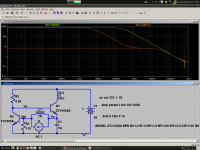
Err.rrh! They recommend using a large inductor to isolate a Voltage source or something with rather less Z than a 'current source'Running the current source in isolation is precisely what I am doing by isolating it from the rest of the circuit with a very large inductor. The use of a large inductor for this purpose is routinely recommended by such luminaries as Rosenstark, Sedra and Smith.
But you aren't measuring its output Z. You are measuring Loop Gain. For this you want to isolate the current source from other stuff. To do this, SHORT OUT IT'S OUTPUT.You cannot obtain valid results by simply connecting the current source to a voltage source via a resistor because that resistor would define the output impedance of the current source giving wildly inaccurate results.
If you want the Loop Gain of the CCS in situ with the effects of OPS, Ccb etc, remove the inductor.
If you want to measure its output Z, then use your inductor and connect the other end to earth.
If you want to know the relative effect of OPS on VAS & VAS on OPS, use your inductor and measure Z on either side of the inductor. I do this in #2877 http://www.diyaudio.com/forums/solid-state/171159-bob-cordells-power-amplifier-book-288.html#post3475959
Err.rrh! Isn't a perfect current source 'a virtual open circuit at all frequencies of interest' while supplying a DC current (or a controlled current for a VCCS etc)?I have never heard of an inductor being described as a current source by anyone; it is no such thing.
Rather, the inductor is a virtual open circuit at all frequencies of interest allowing the output impedance of the current source to be defined solely by the output impedance of the source BJT.
The description of an Inductor as a current source was used by many basic electronic texts in da old days to describe the evolution of simple amplifiers from a single BJT with collector resistor ... to full Class B with LTP i/p .. sorta the Jurassic prelude to Bob's Fig 3.1
It is also the basis of many Golden Pinnae SE amps bla bla.
___________
But why are we discussing this? I think MikeK's analysis is flawed ... but so what? Is this helping us design better amps or understand them better?
[deleted : 104 pg rant about how I analysed all this in my 1000 pg unpublished book on how to grow Cox's Orange Pippins in Antartica
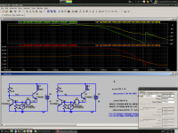
]For the same reason that some voltage regulators/amps oscillate with capacitive loads, I can provoke oscillation in this "unconditionally stable" circuit with a 5uH inductor at the output. Not applicable to most circuits, but worth knowing, and even more worth understanding.
But wait, with your loopgain simulation, we have false results and no way of testing stability into any legitimate load. Oops!
But wait, with your loopgain simulation, we have false results and no way of testing stability into any legitimate load. Oops!
Attachments
Using a current source, as you did in your analysis, is unrealistic and probably explains your somewhat exaggerated loop gain result. I used a more realistic resistor.
Running the current source in isolation is precisely what I am doing by isolating it from the rest of the circuit with a very large inductor. The use of a large inductor for this purpose is routinely recommended by such luminaries as Rosenstark, Sedra and Smith.
You cannot obtain valid results by simply connecting the current source to a voltage source via a resistor because that resistor would define the output impedance of the current source giving wildly inaccurate results.
I have never heard of an inductor being described as a current source by anyone; it is no such thing.
Rather, the inductor is a virtual open circuit at all frequencies of interest allowing the output impedance of the current source to be defined solely by the output impedance of the source BJT.
Mike,
Feeding it with a current source gives us the worst case. Using 22k instead makes only a small difference in the end result, assuming your transistor beta is 100.
A huge inductor is a virtually infinite impedance at AC, but it allows DC current to flow, some in some regard it acts like a current source in the AC domain. My use of the term current source was poorly chosen, but you should have gotten the picture anyway.
As I suggested, you should run your own sanity check with the current source by itself. The complexity of the way in which you are trying to simulate a fairly simple issue is undoubtedly tripping you up.
Remember, with all these powerful tools, garbage in, garbage out. These tools can be mistake magnets. I have seen it all too often. What we see here is a perfect example. Whenever possible, good engineers do a ballpark sanity check, ESPECIALLY if someone else questions their result and explains how to do such a sanity check. This is how we all learn.
Cheers,
Bob
A huge inductor is a virtually infinite impedance at AC, but it allows DC current to flow, some in some regard it acts like a current source in the AC domain.
I afraid thinking of an inductor as a current source is simply absurd and need not be further considered.
I am satisfied from the erroneous responses I have seen on the issue that my approach is wholly correct. We'll have to agree to disagree and leave it at that.
Last edited:
I afraid thinking of an inductor as a current source is simply absurd
Not at all. Inductors are used as effective current sources in switch-mode circuits all the time, especially the ubiquitous clamped inductive load test circuit. What Bob said:
A huge inductor is a virtually infinite impedance at AC, but it allows DC current to flow, [so] in some regard it acts like a current source in the AC domain.
Is 100% true.
Once current is set up in a large inductor it behaves a lot like a current source. You know, just how a very large capacitor that has been previously energised (aka "charged") behaves a lot like a voltage source.
Last edited:
Anyway, I don't owe you an explanation for anything. I have demonstrated to my satisfaction the typical loop gain of the ANF current source. That is sufficient.
Granted , but do you agree that rejecting something
by let say 40dB will forcibly mandate a loop gain
of the same order.
Not at all. Inductors are used as effective current sources in switch-mode circuits all the time, especially the ubiquitous clamped inductive load test circuit. What Bob said:
Is 100% true.
Once current is set up in a large inductor it behaves a lot like a current source. You know, just how a very large capacitor that has been previously energised (aka "charged") behaves a lot like a voltage source.
Excellent analogy, Harry.
Cheers,
Bob
.. from #3430
.. Michael, to get back onto something which hopefully, you don't think everyone else is wrong or cerebrally challenged
.. from #3430
ANF_loop_gain.asc
BJT_models.txt
Apart from Bias Spreader, LTP CCS, Zobels & output L, this might even be a 'real life' working amp.
Michael, can we take this as an example of your views on good practice and your target level of THD/stability? leaving out your L1 of course
This is why I always recommend the jig arrangement where the dut & ref are LTP connected without degen and without base stoppers................ A bipolar undegenerated LTP is obviously more sensitive to matching(s) than the degenerated case. ..........
This is very sensitive and gives good pairs that subsequently don't need trimming for output offset. <2mVdc in a +27dB amp is common.
Distorsion is by the definition creation of new frequencies...
That´s _your_ definition it seems. Phase and amplitude errors are distortions and don´t create new frequencies.
Two links:
http://www.amplifier.cd/Tutorial/Distortion/Distortion_linear.htm
http://www.amplifier.cd/Tutorial/Distortion/nonlinear_distortions.htm
Last edited:
No.Michael, can we take this as an example of your views on good practice and your target level of THD/stability? leaving out your L1 of course
My favorite way to implement the driven cascode is to create a replica of the feedback signal and apply that to the cascode bases. This avoids the need to mess around with the emitter circuit of the LTP.
Cheers,
Bob
Does this work as intended ?? I have found it doesnt offer the same results as the LTP emitters. D Self and Stochino say same.
Seld says in his book that the probable reason is the phase shift in the signal feedback.
Does this work as intended ?? I have found it doesnt offer the same results as the LTP emitters. D Self and Stochino say same.
Seld says in his book that the probable reason is the phase shift in the signal feedback.
Hi manso,
This technique worked like a champ on my MOSFET power amplifier, but I have not tried the other technique on it.
When the replica of the feedback signal is used to drive the cascode, the signal driving the cascode is identical to the signal driving the inverting input of the LTP (assuming no differences in phase shift in the feedback network and the replica network). This means that there is an ever-so-slight difference between this technique and the technique where a sample of the LTP tail signal is used to drive the cascode bases, because the latter is the common-mode signal.
This difference will correspond to one-half of the error signal driving the LTP, which will be a very small difference, especially recognizing that the signal being used to drive the cascode is already there to cancel a second-order effect.
At audio frequencies, this difference will be very small. At higher frequencies, where the error signal is larger in a Miller-compensated amplifier, the difference will become a bit larger.
Some simulations should be able to show the differences between the two techniques.
Can you be more specific in describing how your results were different?
Can you refer me to where Stochino and Self discussed this (I did not see any reference to this in Self's 5th edition).
I'm very interested in learning more about any disadvantages in the replica cascode driving technique as compared to the other technique.
Cheers,
Bob
I'm very interested in learning more about any disadvantages in the replica cascode driving technique as compared to the other technique.
One thing to consider is that bootstrapping with a significantly bandwidth-limited signal leads to negativ input capacitance of the bootstrapped transistor. Unless adressed, this may cause instability.
Samuel
Hi Bob
Indeed your results may be somewhat different because of topology and compensation used.
My results were obtained through simulation of the regular blameless topology. If no-one posts the Self reference before Ill post it tommorrow. If I remember correctly it is in his fifth edition where he took actual measurements of this technique.
- Home
- Amplifiers
- Solid State
- Bob Cordell's Power amplifier book