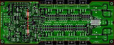
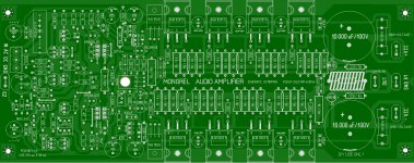
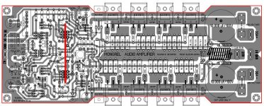
PCB REV 1.6
....as Stanley and Andrew recomanded I have modified PCB like in attachaments")
Regards Alex.
....as Stanley and Andrew recomanded I have modified PCB like in attachaments
Regards Alex.
Attachments
Last edited:
....as Stanley and Andrew recomanded I have modified PCB like in attachaments
Regards Alex.
Is it permissible to make one of these? Is there a sharing of the pcb layout in PDF form?
....as Stanley and Andrew recomanded I have modified PCB like in attachaments
Regards Alex.
Thanks Alex YOUR work is great and very Appreciated HIGHLY...
Just imagine all the variants once I do the whole "shabang" in october !!!
I will do 4 PB60's (2 for me 2 for keen) I already have a pair of BX's , AX's and will most likely do the FX (Koda Super pair). A dedicated amp is alright , but I would never give up my PB250.... If I find something better, the voltage boards are SO much cheaper and easy to make.
Still , very good boards alex , I do believe your prototype will become your favorite "main amp" ... this amp "kicks butt" ...way better than the others that I have built (even objectively). My classical loving oldest daughter was "truly stunned" upon hearing her "Classical thunder" FLAC's on this setup. She was surprised that she only saw them(the amps) on the PC in LT/design phase just a short while ago.
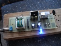
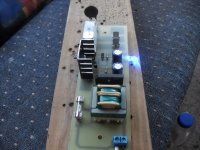
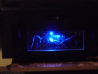
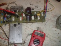
On to the "Board of the day" ,for those with 600VA trafo's and larger ... a simple softstart with it own PS , triggered by the AC and not derived from the main rails.Used a recycled Microwave small trafo ,bridge and the big relay that switches on the magnetron trafo. Microwave "guts" will always have the perfect softstart components ....
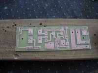
Pix 1 is the flawless , pitfree acid "burn"..
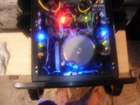
Pix 2/3 are the porno shots of it actually working.
Pix 4 is the schematic. This gives 3 seconds delay after applied AC , charges C2 (220uF) through R1. Since relay is buffered by Q1/2 darlington , many types of junk trafos could be used , just set 13.2v through R1/R2 ratio to get 12V for relay coil.
Last Pix is the superbrite blue led that tells me the main relay has engaged and to warn the user (it's on - BEWARE).
OS
I will do 4 PB60's (2 for me 2 for keen) I already have a pair of BX's , AX's and will most likely do the FX (Koda Super pair). A dedicated amp is alright , but I would never give up my PB250.... If I find something better, the voltage boards are SO much cheaper and easy to make.
Still , very good boards alex , I do believe your prototype will become your favorite "main amp" ... this amp "kicks butt" ...way better than the others that I have built (even objectively). My classical loving oldest daughter was "truly stunned" upon hearing her "Classical thunder" FLAC's on this setup. She was surprised that she only saw them(the amps) on the PC in LT/design phase just a short while ago.
On to the "Board of the day" ,for those with 600VA trafo's and larger ... a simple softstart with it own PS , triggered by the AC and not derived from the main rails.Used a recycled Microwave small trafo ,bridge and the big relay that switches on the magnetron trafo. Microwave "guts" will always have the perfect softstart components ....
Pix 1 is the flawless , pitfree acid "burn"..
Pix 2/3 are the porno shots of it actually working.
Pix 4 is the schematic. This gives 3 seconds delay after applied AC , charges C2 (220uF) through R1. Since relay is buffered by Q1/2 darlington , many types of junk trafos could be used , just set 13.2v through R1/R2 ratio to get 12V for relay coil.
Last Pix is the superbrite blue led that tells me the main relay has engaged and to warn the user (it's on - BEWARE).
OS
Attachments
Hi,
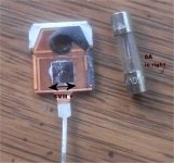
the modified input pins look like 0.2inch pitch.
0.1inch pitch is what Jens used and it works very well.
Swap the DC input with the AC input, if possible.
Solder the input twisted pair to the AC IN and Sig Gnd, on the bottom side.
Leave the shorting plug hanging on the top Sig Gnd pin.
This is AC coupled.
Move the shorting plug to across DC IN to AC IN.
This is DC coupled.
Move the shorting plug to across AC IN to Sig Gnd.
This is the input shorted for testing with Zero signal volts and Rs=0r0
Hi Os,
please add me in for quite a few experimental versions.
This is cool , we don't have to rely on just simulations anymore. Maybe "uncle charlie will concede that numbers might really matter a bit after all.
What I will do next is commit "mongrel labs" in my barn (man cave) , along with a pair of PB60's , A nice set of Sony 2 -ways with soft dome tweeters , and my slew of Voltage stages to further development.
Below is the FX , a strange "rabbit hole" adventure , just like the GX. There is a large following of Koda "modders" that even blog about it. Must be something motivating them. The FX is as good as done ... same as that softstart.. 1 hour for the boardwork , 1 hour to make the dang thing , that's it. !
I can't let the virtual perfection of the GX slow me down in my exploration of the other great designs out there.I still can't believe that the GX sounds as good as it does , I only had a "hint" of what to expect by it's distortion profiles (both FFT and total THD20) , and took a chance.... glad I did.
OS
Attachments
Is there any benifit from adding additional output devices (over the PB250) if running on a about +/-75V DC rails. I have 2x 1KVA supplies I'm thinking of using for this?
Thanks
Rob
I would not go as far as some and put 10 pairs on the PB250's MJE15032/33 driver pair. 6 pairs at 70-75V would be preferable to my 4 pair for continuous safe SOA at 4R... I DID run my 2 pair of 15" 3 -ways in parallel for many hours to "run the snot" out of my wimpy 4 pair setup ... It did survive. I normally just run 8R loads with the desire for killer headroom , so my choices serve me. Another good setup would be 4 pair NJW21193/4 .. about 50% more SOA @ 75V , same package.
The 6 pairs of NJW's mentioned above are right at the SOA limits of the MJE driver set at 2-4R @ 75V. Lower beta MJL-XXX (4302 /21193) would most likely experiance a little "droop" , especially at 2R.
Anything beyond this would require a triple.. absolutely!
OS
Last edited:
PDF file for PB120LP
Hi all,
I would like to share my version of PB120 with two pairs of OTs and Capacitance Multiplier. I will build a GX together with this PB120LP and I am still waiting for some parts.
I think that this modular design is great for prototyping.
Happy experimenting.
Cheers, Stanley
Hi all,
I would like to share my version of PB120 with two pairs of OTs and Capacitance Multiplier. I will build a GX together with this PB120LP and I am still waiting for some parts.
I think that this modular design is great for prototyping.
Happy experimenting.
Cheers, Stanley
Attachments
I blew one channel up ... arggg!!
Catastrophy , one slip and POOF!!
Not a bad chain reaction , actually , just the fuses went , then the first pair of NJW's ... and it took out 1 flyback diode.
I got to see what a hard short did to it. NO damage to either the cap multiplier or the GX module (fired it back up with 1 pair OP's). I won't use the remaining 3 pairs for this amp even as they test good. Have 16 more pairs.. so no sweat.
I am actually glad to see the amp blows up "gracefully".
OS
Is this how the mountains became smokey?
Smokey
Hope not that much!Is this how the mountains became smokey?
Attachments

Hi Repeet,
Assuming that you have a 30-0-30V-AC 225VA transformer, one transformer is good enough for stereo 64W into 8 ohm.
If you are driving 4 ohm speaker, then one transformer is only good enough for one channel at 115W, you will need both transformer for stereo. You will have better result by using two transformer & two PSU boards.
Again this is a simplistic as we have not taken accounts of SOA of different output transistors. I prefer to use two pairs of OTs as it has better SOA & better driving capability for "difficult" load.
I saved the following table from Quasi's NMOS350 thread.
Power selection guide.
This table should be used as a power configuration guide. Powers shown are approximate and probably maximum depending on the size and quality of the power supply. Power have been estimated to real world applications using a reasonable power supply.
Definition of Reasonable:
Transfomer VA = total output power x 1.5. DC smoothing section = 80uF capacitance per DC rail per watt of output power.
Example: A stereo amplifier running 60 volt rails capable of 165 watts into 8 ohms per channel will require a 500va transformer and a capacitor bank of 13,200uF per rail or 26,400uF per amp module or 52,800uF for a stereo set-up.
AC volts; DC rail volts; 8 ohm Pwr; OT req; 4 ohm Pwr; OT req
30 40 64 2 115 2
33 45 82 2 146 4
37 50 107 2 192 4
40 55 128 2 230 4
44 60 160 2 290 4
47 65 185 4 335 6
51 70 223 4 405 6
54 75 253 4 460 8
58 80 297 4 540 8
61 85 330 6 600 10
Cheers, Stanley
Last edited:
Thanks Stanley, yes I think your 2 output board will fit the bill nicely with 2 x 30-0-30 trafo's. It will be driving 6ohm speakers. This will be my first attempt at etching my own boards, sounds like fun. This amp will be replacing my first DIY amp in my 2nd room system, a NAP140 clone that I have been quite happy with. MY amp in my main room is a SKA GB150D which I am extremely happy with. I wonder how this one will compare?
I know I must be on the right path if those "down under" want to build. Upon redoing and cleaning all the flux off of everything (that and a piece of aluminum milling - arggg!) The bias is even more stable , can't shake 20mV (75mA w/.27R emitter resistors) from 10C in the morning to 35C in the afternoon. If one would have to service these amps , they are so easy.
On the test jig ... 17mv @ 45 volt rails (pix1)
The poor NJW0281 had bubbled tinplate on the thermal inteface .. it must of got real hot in the couple seconds before the fuses failed. (pix2 below) note the nearly 1/4" (6-7mm) dies ... no fake here!
(Pix 3) happy again... Damn .. I had to build three amps , will be MUCH more careful now... a lesson learned.
OS
Upon redoing and cleaning all the flux off of everything (that and a piece of aluminum milling - arggg!) The bias is even more stable , can't shake 20mV (75mA w/.27R emitter resistors) from 10C in the morning to 35C in the afternoon. If one would have to service these amps , they are so easy. On the test jig ... 17mv @ 45 volt rails (pix1)
The poor NJW0281 had bubbled tinplate on the thermal inteface .. it must of got real hot in the couple seconds before the fuses failed. (pix2 below) note the nearly 1/4" (6-7mm) dies ... no fake here!
(Pix 3) happy again
... Damn .. I had to build three amps , will be MUCH more careful now... a lesson learned.OS
Attachments
Hi,
I don't expect a fuse to save a transistor when an accidental short occurs.
Your 8A fuses in the supply rails seem very high.
I use supply rail fast fuse rating = 50% of Ipk, where Ipk=Vpk/Rload.
For a two pair output stage possibly going to 100W into 8ohms Ipk~5Apk.
Therefore I would use an F2.5A fuse for 8ohm speakers.
For 100W into 4ohm I calculate that to be F3.5A.
Quasi uses the same rational. His fuse rating = 50% of Irms, which reduces the 4ohm fuse to F2.5A
Hi,
I don't expect a fuse to save a transistor when an accidental short occurs.
Your 8A fuses in the supply rails seem very high.
I use supply rail fast fuse rating = 50% of Ipk, where Ipk=Vpk/Rload.
For a two pair output stage possibly going to 100W into 8ohms Ipk~5Apk.
Therefore I would use an F2.5A fuse for 8ohm speakers.
For 100W into 4ohm I calculate that to be F3.5A.
Quasi uses the same rational. His fuse rating = 50% of Irms, which reduces the 4ohm fuse to F2.5A
I agree ,andrew. they are what I had on hand , This is a 200w setup so I was thinking 7A. the 8A did save any wiring , PCB traces... and actually saved the speaker...
I am going all the way this time , Dr. bora's omni protect will be the recommended accessory to the mongrel lineup.
PS , andrew , you gotta build this GX , I just fine tuned the trimmers on it to balance the input pair with the scope... WOW!
NO more blameless or DX style bootstraps for me.
OS
Last edited:
- Status
- This old topic is closed. If you want to reopen this topic, contact a moderator using the "Report Post" button.
- Home
- Amplifiers
- Solid State
- The MONGREL (supersym II)