This subject started in another thread
Super Regulator, collecting the facts
but it seems a discussion on its own, so I moved it here. The idea is to build a low noise amplifier with 60dB (1000x) to use it as for noise measurements. Initially I built the circuit from the Linear Technology application note 83
http://cds.linear.com/docs/Application Note/an83f.pdf
but I wanted something with even lower noise so I put together a simple discrete circuit using paralleled jfets (2sk170v). However, I used no feedback so setting the gain to 60dB with low tolerance is something that relies on a very good AC voltmeter. Jan recommended using feedback to be able to calculate and implement the gain accurately. What comes next has been moved from the other thread.
This is what I built 🙁
The subtler issues escape me, as you can see.
Attachments

This is what I built 🙁
The subtler issues escape me, as you can see.
Yes that's open loop. Is this the measurement amplifier you mentioned before?
jd
Yes that's open loop. Is this the measurement amplifier you mentioned before?
jd
Yes. I might have to stick with the opamp one, to avoid all those issues.
Yes. I might have to stick with the opamp one, to avoid all those issues.
Try this: multiply the two collector resistor values by 10. Replace Q2 with an NPN. Feedback the output signal via 6.8k ohms to the input stage sources.
Rough maths says you've got about 59.92dB gain.
Then put 400 or 500 ohms in parallel with the 6.8 ohms source resistor, should get you at exactly 60dB.
I haven't looked at DC stuff so try first with cap coupling at all the sensitive points 😉
jd
is that r5 & r12multiply the two collector resistor values by 10.
q2 is a common collector (= emitter follower).
Are you suggesting that it becomes a common emitter to generate some voltage gain?
Last edited:
is that r5 & r12
q2 is a common collector (= emitter follower).
Are you suggesting that it becomes a common emitter to generate some voltage gain?
yes R5 & R12. I think you need to invert the output signal to make the feedback negative, and in my stupidity I said change Q2 to an NPN which, as a common collector, doesn't invert the signal of coure. Leave Q2 as-is, use a collector resistor equal to the emitter resistor and take the feedback from the collector. If the output sticks to the supply I've got it wrong and then take the feedback from Q2 emitter 😉
jd
Just got back from getting some parts. I'll try your suggestions and let you know.
OK, so I simulated the changes. Adding 6k8 feedback from between the collector of Q2 and a 100R resistor to the source of jfets in stage one doesn't change the gain. Making R5 = 6k and R12 = 9k1 kills everything. Are you sure about this?
OK, so I simulated the changes. Adding 6k8 feedback from between the collector of Q2 and a 100R resistor to the source of jfets in stage one doesn't change the gain. Making R5 = 6k and R12 = 9k1 kills everything. Are you sure about this?
Sure? That'll kill the gain again, I think.
jd
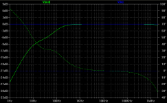
Yes, but look at the response curve IKO has provided -- and where does 6.8R x 470uF work out?
If I remove C5 with no feedback, it will indeed kill the gain. But with the 6k8 feedback removing C5 actually increases the gain by about 3.5dB.
Just got back from getting some parts. I'll try your suggestions and let you know.
OK, so I simulated the changes. Adding 6k8 feedback from between the collector of Q2 and a 100R resistor to the source of jfets in stage one doesn't change the gain. Making R5 = 6k and R12 = 9k1 kills everything. Are you sure about this?
Yes but I suspect that the DC conditions are all wrong now. I'll see if I can work that out later.
What are the collector voltages now with the increased R?
jd
@JW the 470uF doesn't come into play until above 50Hz or so, correct?
Yes but I suspect that the DC conditions are all wrong now. I'll see if I can work that out later.
What are the collector voltages now with the increased R?
10 x R gives V(a11) = 124mV (was 4.89V before) and V(a12) = 11V (was 20.4V before).
There is (should be) about 31mA going through the four jfets.
10 x R gives V(a11) = 124mV (was 4.89V before) and V(a12) = 11V (was 20.4V before).
There is (should be) about 31mA going through the four jfets.
OK, try with R5 just a few k, increase Vcc to 40V or so. The initial object is to get Q4 back out of saturation. Even a few volts would do to test gain.
I don't think there's 30mA though the fets. Can you check voltage across the source R?
jd
Oh, you mean in the real circuit? There R5 = 750R, and there is 17.7V across it (23.6mA). Jan, it would be nice to stay with voltages that are possible with batteries, given that this would be a low noise amp. Currently I'm using two 12V lead acid batteries in series. I could, I guess, go to 36V by adding another battery, or maybe 48V with two more batteries, but only if really necessary (they are kind of big, these batteries, and htey would have to fit in the box). There are some pictures posted earlier.
Oh, you mean in the real circuit? There R5 = 750R, and there is 17.7V across it (23.6mA). Jan, it would be nice to stay with voltages that are possible with batteries, given that this would be a low noise amp. Currently I'm using two 12V lead acid batteries in series. I could, I guess, go to 36V by adding another battery, or maybe 48V with two more batteries, but only if really necessary (they are kind of big, these batteries, and htey would have to fit in the box). There are some pictures posted earlier.
No I mean in the sim, that's what we are talking about so far, right?
I was going to get the circuit in the ballpark, therefor suggestion to increase Vcc. When it's all in its linear range we can tune it to the selected voltage.
Well, must go to bed now, tomorrow is another day!
jd
Thanks Jan, and good night! I think I'll move these posts to a new thread, to not pollute the super-reg developments.
I've done some experiments with various jfet input preamps to test some ideas and went back to Dennis Colin's low noise preamp for a look. This time I noticed something off. Has anyone built Dennis Colin's low noise preamp?
http://www.audioxpress.com/magsdirx/ax/addenda/media/colin2764.pdf
http://www.audioxpress.com/magsdirx/ax/addenda/media/colin2764.pdf
Basically, I'm confused by resistor R2. Should it not be below the input to U1's input capacitor (C5) and above the jfets, as I show in the attached image? That would make sense to me, as it's supposed to provide a 40dB gain, in conjunction with the 1k5 resistor in U1's feedback.
Also, what is C2 for?
http://www.audioxpress.com/magsdirx/ax/addenda/media/colin2764.pdf
http://www.audioxpress.com/magsdirx/ax/addenda/media/colin2764.pdf
Basically, I'm confused by resistor R2. Should it not be below the input to U1's input capacitor (C5) and above the jfets, as I show in the attached image? That would make sense to me, as it's supposed to provide a 40dB gain, in conjunction with the 1k5 resistor in U1's feedback.
Also, what is C2 for?
Attachments

the k170 look like a low noise buffer in front of the 797.
There is no voltage gain in the buffer.
There is no voltage gain in the buffer.
There was an update to Colin's article in the letters section -- mistake on the schematic. (Xpress Mail, 7/07) The value of R8 is incorrect, should be 51.1K.
Daniel Dufresne's corresondence in (Xpress Mail, AX 8/07) -- suggested using a red LED instead of the 1N4148 diodes for clamping. This will raise the input impedance of the preamp.
If you want to measure noise with this amplifier, consider using 10,000uF for C3. This cap sets the lower cutoff.
I measured the noise of the amplifier at just under 1nV/RtHz. Unless you're at the Lawrence Livermore Laboratories, running out the noise statistics to 3 significant places is just silly. It's stochastic!
It's always helpful to have the subsequent issues to these articles, since gremlins and tweaks always manage to appear a month or so later.

- Home
- Amplifiers
- Solid State
- Simple 60dB discrete low noise amplifier (lna)