Perhaps something simple like this can work.
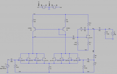
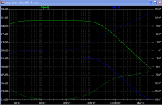
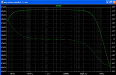
High first stage gain using paralleled 2SK170V jfets (or perhaps bf862 better). Two low noise pnp, not necessarily bc560c, but I didn't have a model for any of the 2saX bjts. The total open loop gain is about 88dB, as seen in the second attachment. Using a resistor divider to get about 60dB, as in the third attachment. The second stage is not directly coupled. I did try, but failed to come up with a simple directly coupled second stage that would work as well as this.
High first stage gain using paralleled 2SK170V jfets (or perhaps bf862 better). Two low noise pnp, not necessarily bc560c, but I didn't have a model for any of the 2saX bjts. The total open loop gain is about 88dB, as seen in the second attachment. Using a resistor divider to get about 60dB, as in the third attachment. The second stage is not directly coupled. I did try, but failed to come up with a simple directly coupled second stage that would work as well as this.
Attachments
Hi Iko
I don't see what the problem was with the performance of the circuit in post#1, aside from the low-frequency roll-off, which would be easy to fix by increasing C5 (and maybe C1 as well).
With the latest circuit, won't the DC voltage at point a11 be more-or-less undefined?
Cheers - Godfrey
I don't see what the problem was with the performance of the circuit in post#1, aside from the low-frequency roll-off, which would be easy to fix by increasing C5 (and maybe C1 as well).
With the latest circuit, won't the DC voltage at point a11 be more-or-less undefined?
Cheers - Godfrey
Yes, the circuit in post #1 worked, but the fly in the soup was not so good stability of the gain. So feedback was recommended, hence the resistors Rf1 and Rf2.
The voltage drop across the bjt shouldn't be large, so there should be enough voltage across the jfets to do their thing, I think. But I haven't built this one yet; I'll try it first thing next week.
godfrey said:With the latest circuit, won't the DC voltage at point a11 be more-or-less undefined?
The voltage drop across the bjt shouldn't be large, so there should be enough voltage across the jfets to do their thing, I think. But I haven't built this one yet; I'll try it first thing next week.
I don't think the so far posted schematics are a particularly suitable start to implement a low noise amplifier--e.g. have you looked at the PSRR of these designs?
Is there a particular reason why it *needs* to be fully discrete? I would not have any difficulties to sketch such an amplifier (that actually works) for you but I don't see any justification for it. Rather I'd suggest you look at this: www.sg-acoustics.ch/analogue_audio/test_gear/pdf/lab_preamp_100x_lp_r1.pdf
The first stage (everything to the left of C6) could be easily modified for 60 dB gain and lower noise, with overall much better behaviour than what we've seen so far in this thread.
Samuel
How about a circuit based on this idea: http://www.diyaudio.com/forums/solid-state/129228-measuring-low-noise-2.html#post1603576
Has the benefit of balanced inputs and some common mode suppression
Has the benefit of balanced inputs and some common mode suppression
Thanks for your advice Samuel. Just to be clear, my perspective is that of a beginner, which I am, hence, there will be questions which you may find trivial and/or annoying. One my motivations is to learn something from this exercise.
Yes, but didn't concern myself much with PSRR because the supply is intended to be batteries, and the whole thing be cased in a metal box. It would be nice to keep the circuit simple, if possible to get away without much PSRR. What do you think?
Certainly not, it does not need to be anything in particular if it achieves the objective. Though my own preference would be for a simple discrete design.
Teaching value is a good justification, IMHO.
I will look at your suggestion and come back, hopefully not with many questions.
I don't think the so far posted schematics are a particularly suitable start to implement a low noise amplifier--e.g. have you looked at the PSRR of these designs?
Yes, but didn't concern myself much with PSRR because the supply is intended to be batteries, and the whole thing be cased in a metal box. It would be nice to keep the circuit simple, if possible to get away without much PSRR. What do you think?
Is there a particular reason why it *needs* to be fully discrete?
Certainly not, it does not need to be anything in particular if it achieves the objective. Though my own preference would be for a simple discrete design.
I would not have any difficulties to sketch such an amplifier (that actually works) for you but I don't see any justification for it.
Teaching value is a good justification, IMHO.
Rather I'd suggest you look at this: www.sg-acoustics.ch/analogue_audio/test_gear/pdf/lab_preamp_100x_lp_r1.pdf
The first stage (everything to the left of C6) could be easily modified for 60 dB gain and lower noise, with overall much better behaviour than what we've seen so far in this thread.
Samuel
I will look at your suggestion and come back, hopefully not with many questions.
How about a circuit based on this idea: http://www.diyaudio.com/forums/solid-state/129228-measuring-low-noise-2.html#post1603576
Has the benefit of balanced inputs and some common mode suppression
Thanks Martin, it doesn't seem to be really low noise? It would be nice to approach or better an ad797 in terms of noise.
Thanks Martin, it doesn't seem to be really low noise? It would be nice to approach or better an ad797 in terms of noise.
Hello Ikoflexer, I think you can get pretty low noise and with balanced inputs it will have less noise pickup (Walt Jung used a balanced input amp for his noise measurements which is why I got interested). Though I have not built it yet I simmed version that have below 1nV/rt Hz noise performance with 2 paralleled 2SK170/2SK389 and a LME49860. This is pretty good for a balanced circuit (as much as you can trust sims) and as good or better than an AD797. I have the parts lying around but no time yet to breadboard it.
Rather I'd suggest you look at this: www.sg-acoustics.ch/analogue_audio/test_gear/pdf/lab_preamp_100x_lp_r1.pdf
The first stage (everything to the left of C6) could be easily modified for 60 dB gain and lower noise, with overall much better behaviour than what we've seen so far in this thread.
Hello Samuel,
As I am new to design so this question might be silly of me, but here goes...
Where does the input stage DC flow? It says 1mA above Q2, so that will flow through Q2 and Q1, but then it is blocked by C5, so where does it go?
It doesn't seem to be really low noise?
As shown it is indeed rather noisy as it has low gain. However to complete the schematic you'll need to add a gain setting resistor between the two sources of the input pair.
Instrumentation amplifiers are nice for their CMRR but they have higher voltage noise compared to a single-ended input (such as shown in my schematic). It's all a matter how low the noise really needs to be.
Where does the input stage DC flow? It says 1mA above Q2, so that will flow through Q2 and Q1, but then it is blocked by C5, so where does it go?
Through R6. There is a DC offset at the output of U1A because of this (and the Vgs of the input JFET) but this is blocked by C6.
Samuel
Last edited:
Through R6. There is a DC offset at the output of U1A because of this (and the Vgs of the input JFET) but this is blocked by C6.
So if it flows through R6, then it must flow into the output of the op-amp and then to the negative power rail via the lower output device in the op-amp output stage. That is not very intuitive! But OK, I begin to understand a little, so thank you for the reply.
J.
As shown it is indeed rather noisy as it has low gain.
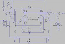
Simple version, with gain of 1000, sims to below 1nV/rt Hz (at 10KHz its an optimistic 0.8nV). You can off course add more jfets in parallel, though with diminishing return. 1000 may be too much gain for me, I am thinking of adding a buffer and lowering the feedback resistors R5/R8 to, say 100 Ohms or so. Improvements/comments are welcome:
Attachments
Simple version, with gain of 1000.
You should set gain with a resistor between the sources of the input transistors, not by lowering R6/R7. Otherwise I'd say this will kill CMRR.
Samuel
Hello Ikoflexer, I think you can get pretty low noise and with balanced inputs it will have less noise pickup (Walt Jung used a balanced input amp for his noise measurements which is why I got interested). Though I have not built it yet I simmed version that have below 1nV/rt Hz noise performance with 2 paralleled 2SK170/2SK389 and a LME49860. This is pretty good for a balanced circuit (as much as you can trust sims) and as good or better than an AD797. I have the parts lying around but no time yet to breadboard it.
Hi Martin, I don't know how much I can trust the simulator for noise results (and I'm not shy using the simulator in general). Balanced input is nice, when needed, but I probably would want it single ended. I don't know too much about these things, but this one doesn't have really high gain in the first stage. Then the 4k drain resistor would worry me too. I'm not dismissing it, let's keep the discussion open.
The Jung circuit is pretty consistent at 1.6 to 2.0 nv/Rt Hz. The Dennis Colin circuit averages just under 1nV/Rt Hz but is not as consistently even through the bandwidth. There are some similarities between Scott's BF862 circuit and that in the AN-124 application note. I have the AN-124 design in the works -- found a really low leakage electrolytic for the input.
You can build Scott's circuit with 2Sk170's if you don't want to work with SOT23 devices.
You can build Scott's circuit with 2Sk170's if you don't want to work with SOT23 devices.
I don't know how much I can trust the simulator for noise results
Well, there is only one way to find out. My reasoning for going balanced was because of lower noise interference (see also Walt Jungs articles on regulators) compared to single ended.
Having said that this is pretty much the same discussion as for, say, balanced vs. single-ended phono input stages. The balanced version has a noise penalty of 3dB (-6dB signal but +3dB because twice the input devices in parallel). Fundamentally the circuit is a variation of the many low noise phono input stages with 2SK170 / BF862, etc., so from that perspective I am quite confident that it will still be as low noise as expected.
Then the 4k drain resistor would worry me too.
You mean 1K4? Here the signal is already amplified by the input transistors by 20+ db so increasing this resistor should decrease noise, as amplification goes up linearly and noise only by the square root of the resistance (unless I am mistaken?).
You should set gain with a resistor between the sources of the input transistors, not by lowering R6/R7. Otherwise I'd say this will kill CMRR.
A 2SK170 has ca 55 Ohms equivalent noise resistance, 2 in parallel should be below 30, so I was thinking of increasing R6/R7 to some 3-5 Ohms without increasing noise much. Since I can match FETs for both halves pretty closely CMR might still be pretty good. Also, I "thought" I could improve CMR by placing a small value pot (say 200 Ohms) under input resistors R11/R12 to correct for their tolerances?
Last edited:
You mean 1K4? Here the signal is already amplified by the input transistors by 20+ db so increasing this resistor should decrease noise, as amplification goes up linearly and noise only by the square root of the resistance (unless I am mistaken?).
Right, I was looking at the original circuit you pointed to, not the one you modified. Still, I personally would increase the gain in some other way than by a larger drain resistor, if possible.
Guys, two additional feature would be important to me:
1) to be able to precisely dial in the 60dB gain, like it can be done with an opamp, ideally using a couple of precision resistor
2) stable gain; i.e. insignificant change in gain from variations in component values due to temperature, supply voltage, etc.
Samuel, Martin, you each suggested a circuit. What do you think?
- Home
- Amplifiers
- Solid State
- Simple 60dB discrete low noise amplifier (lna)