So if it flows through R6, then it must flow into the output of the op-amp and then to the negative power rail via the lower output device in the op-amp output stage. That is not very intuitive!
Indeed, but that's how it is. The schematic suggests that the output of the opamp is at a higher DC voltage than the source of the input JFET, but that's not the case--it is at a lower voltage.
Here the signal is already amplified by the input transistors by 20+ db so increasing this resistor should decrease noise, as amplification goes up linearly and noise only by the square root of the resistance (unless I am mistaken?).
Perfectly true. The resistors are at a current node, hence higher resistance gives lower noise. Only the required common-mode range limits this resistor value, and it should be chosen as high as possible.
Still, I personally would increase the gain in some other way than by a larger drain resistor, if possible.
You're mixing up open-loop and closed-loop gain. The value of the drain resistors increases (low-frequency) open-loop gain but not closed-loop gain. The later is determined by the feedback network.
To be able to precisely dial in the 60 dB gain, like it can be done with an opamp, ideally using a couple of precision resistor.
Both suggestion do that.
Samuel
You're mixing up open-loop and closed-loop gain. The value of the drain resistors increases (low-frequency) open-loop gain but not closed-loop gain. The later is determined by the feedback network.
Samuel
You're jumping to conclusions fast. Since I was talking about first stage gain, obviously I was referring to the open loop gain.
Both suggestion do that.
Samuel
Yours doesn't employ the idea of having large open loop gain and then setting the closed loop gain via global feedback and the ratio of two resistors. Unless I'm missing something, your circuit gain adjustment is done by trimming R8, local feedback, hence for precise gain setting you need to be able to accurately measure a voltage and then 100 times that. Your circuit will also be subject to gain changes due to small 0.25V in supply voltage, and probably less to temperature variations of the jfet. Again, I'm not versed in analogue design so I might be missing some subtleties.
Unless I'm missing something, your circuit gain adjustment is done by trimming R8, local feedback, hence for precise gain setting you need to be able to accurately measure a voltage and then 100 times that.
Look at it again. R6-R8 set *global* gain as R6 is taken from the opamp output. The opamp has (besides C4) no local feedback so would work (or rather: not work) open-loop.
The Wurcer circuit works very similarly, just in a balanced fashion.
Your circuit will also be subject to gain changes due to small 0.25 V in supply voltage, and probably less to temperature variations of the JFET.
Sorry, I don't understand where your 0.25 V figure comes from. The circuit as shown has *exceptionally* good PSRR over a wide frequency range down to DC due to several means:
* The voltage drop across R4 (which sets Q1 drain current) is very well fixed by use of a CCS (Q4) and a large capacitor (C3).
* The drain of Q1 is cascoded by Q2. This isolates it from any drain voltage variation due to positive supply ripple.
* C4 is not connected to the collector but the emitter of Q2. At HF this has a drastic positive effect on PSRR as the local feedback of U1A (and hence the output voltage of this opamp) is not referenced to the positive supply (where ripple would be coupled to the output) but effectively to the input voltage.
I'll challenge you to show me a circuit with similar complexity but better PSRR.
Similarly there's near-zero dependence of gain on temperature besides the tempco of R6-R8 as Q1 is enclosed in a global loop.
Samuel
Indeed Samuel, the PSRR is about -18dB from 100Hz to about 2kHz and then it goes lower from there, due to the bypass caps in the supply. OK, I take back my comment. Also I checked the gain stability, and I would find that acceptable.
One thing though. The gain seems to be mostly (if not completely) produced by U1. Then U1's input voltage noise would dominate, so the best we can do is an AD797. I was hoping to do better than that. You mentioned that the noise can be improve, but I don't see how. Normally I would have though that paralleling some more 2sk170 would result in lower noise, but since the jfet doesn't provide most gain, then the parallel setup would not help. I already have looked at another circuit which uses the jfet (almost) as a buffer (Dennis Colin's input stage is very much like yours).
Edit: Samuel, may I ask how you would modify it to get 60dB gain?
The PSRR is about -18 dB from 100 Hz to about 2 kHz.
That'd be very bad PSR! Where did you get that figure from?
The gain seems to be mostly (if not completely) produced by U1.
No. The gain of Q1 is (very approximately) R3/(R7+R8). So the voltage noise of U1A is ~100x (real figure is lower) less important than that of Q1.
The best we can do is an AD797.
Again no. The opamp sees a source impedance of about the value of R3. An AD797 has about 1 dB higher noise figure than the OPA2134 under this condition because of its high current noise. I do see this all the time--people just look at voltage noise specs and forget about current noise. Both current and voltage noise have *exactly* the same importance. It just depends what the source impedance is.
You mentioned that the noise can be improve, but I don't see how.
First of all increasing the gain lowers noise (refered to the input). That's done as in any opamp circuit--adjust R7/R8 for the correct ratio to R6 (actually I'd just skip the trimmer and use a single resistor).
I already have looked at another circuit which uses the JFET (almost) as a buffer.
Again it is not a buffer, neither in Collin's nor in my design. It is a common-source stage with considerable gain.
Samuel
That'd be very bad PSR! Where did you get that figure from?
I just simulated the PSRR. I used an LT1028 model instead of the OPA134, but that shouldn't make that much of a difference.
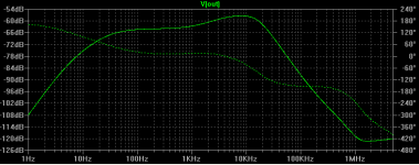
Edit: went back and checked the sim, found an error, sorry about that; this time with OPA134, the PSRR looks better (attached).
Attachments
Rather I'd suggest you look at this: www.sg-acoustics.ch/analogue_audio/test_gear/pdf/lab_preamp_100x_lp_r1.pdf
Samuel, you almost stole my idea
 ( just joking of course
  ).
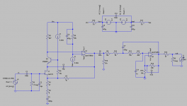
).Here's a glimpse in the HPS 5.1 headamp, quickly adapted for a gain of 60dB (I'm using 32dB as a standard). Compensation is for an unity loop gain of 1.1MHz.
This, coupled with a noise cancelling power buffer (essentialy a Sziklay pair that includes the power device Rbb in the current feedback loop, greatly reducing the equivalent noise) will provide under 0.3nV/rtHz. You would of course note the servo and the lack of a DC blocking cap in series with the feedback resistor (a big nono in my book, electrolytics, and in particular the large ones, have a very nasty habit to be microphonic).
The HPS 5.0 head amp (identical to the below, minus the extra PSRR circuitry, relying only on the power buffer noise rejection) already measures slightly over 0.3nV/rtHz, so this is about all you can reasonable get from paralleling JFETs. Note that the BF862 device has an Ciss of only 10pF (compared to 70pF for 2SK170) and that the real world circuit has (for each JFET) 1uH inductances as gate stoppers, to avoid possibly 100-200MHz oscillations.
HPS 5.0 is now finalized and will soon be available on my web site, HPS 5.1 is now under construction.
All ultra low noise, DC coupled, high gain amps have a common (not obvious from simulations) small issue: very low frequency fluctuations. These are due to the rapidly increasing 1/f noise with decreasing frequency, while the gain is high and constant down to DC. If annoying, a LF roloff is the only way to avoid these fluctuations. In the particular case of a MC/MM preamp, implementing somewhere downstream the recommended rumble filter at about 20Hz helps.
Attachments
Last edited:
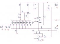
Is the model of Q5 correct?
My bad, it's ZXT690 (the NPN, ZXT790 is the PNP in the pair). It's a 5A and 150MHz SMD device, chosen for the very low noise (as many other power devices) .
Attached.
Well the power supply caps are connected wrong but I'd exclude them anyway in simulation at adding RC filters is a trivial and not particularly interesting solution to increase PSR. I'd look however at the PSR of the first stage alone without the filter.
You almost stole my idea.
Great minds do think alike. You might however consider my compensation scheme for better PSRR (it has some issues but worked very well in the implementation I've shown); that might free you from the power supply issues.
Chosen for the very low noise.
Why should low voltage noise in this position matter?
Samuel
Question for syn08: if you're familiar with the 2sc1571, would it be suitable noise wise to use for Q5 instead of the ZXT690 which I have none at the moment?
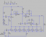
Edit: actually I modified the circuit a little more, to power it from two 12V batteries. Added a buffer after the first stage, seems to get closer to the theoretical 60dB this way. I happen to have a bunch of opa4134s on hand, so I'm planning to use one to cover the second stage, servo, and buffer.
Edit: actually I modified the circuit a little more, to power it from two 12V batteries. Added a buffer after the first stage, seems to get closer to the theoretical 60dB this way. I happen to have a bunch of opa4134s on hand, so I'm planning to use one to cover the second stage, servo, and buffer.
Attachments
Well, here it is -- a 20dB and a 60dB -- in one cookie tin.
I was expecting a bit less noise on the 60dB amplifier -- it's around 1.6nV/RtHz
An externally hosted image should be here but it was not working when we last tested it.
An externally hosted image should be here but it was not working when we last tested it.
I was expecting a bit less noise on the 60dB amplifier -- it's around 1.6nV/RtHz
I was expecting a bit less noise on the 60dB amplifier -- it's around 1.6nV/RtHz
Which circuit?
I finished the first stage now, cookie tin too, at a nice 33dB open loop gain.
Which circuit?
An externally hosted image should be here but it was not working when we last tested it.
Question for syn08: if you're familiar with the 2sc1571, would it be suitable noise wise to use for Q5 instead of the ZXT690 which I have none at the moment?
Edit: actually I modified the circuit a little more, to power it from two 12V batteries. Added a buffer after the first stage, seems to get closer to the theoretical 60dB this way. I happen to have a bunch of opa4134s on hand, so I'm planning to use one to cover the second stage, servo, and buffer.
No, potentially it won't stand the power. Noise here counts only if you are looking at 0.2-0.3nV/rtHz, otherwise use whatever you have that takes the power (~1W)
With that opamp follower you just spoiled the entire design (and the noise performance as well). The whole key is using the first low noise stage as a transconductance amp, and using the second stage very low input impedance (also shunting the opamp voltage noise!) the open loop gain is gm*R17, where gm~2*Id/Vt. The opamp current noise feeds R17 as well, but the noise voltage effect is very smal because a) it's a fet input opamp, noise currents are small and b) the equivalent resistor is divided by the opamp open loop gain.
There is no point feeding the input stage (and referring the input to) -Vee. Instead, ground will do just fine.
The Wenzel circuit has been around a while. Low Noise Amplifier eBook Downloads
Iko - Samuel is right about the gain resistor across the sources in that circuit.
Iko - Samuel is right about the gain resistor across the sources in that circuit.
- Home
- Amplifiers
- Solid State
- Simple 60dB discrete low noise amplifier (lna)