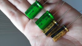
2200uF is too high ? I have some 2200uF / 6.3V fine gold
You can use it just add 100nF in parallel, there is no to high value best is without cap with DC servo.
2200uF is too high ? I have some 2200uF / 6.3V fine gold
wow! Envy you
") ... it might just be perfect....why dont you share impressions with those beauties? Just dont trim the leads, you may like to preserve them!
... it might just be perfect....why dont you share impressions with those beauties? Just dont trim the leads, you may like to preserve them!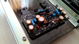
I'll let you know ... forehead Fine gold and ES BP in my ax11
i must say ... exquisite build... enjoy the sound! (with vishay res and those nichi fine caps!)
I'll let you know ... forehead Fine gold and ES BP in my ax11
Excellent work! Vishay RN60's and Nichicon FG's are top choice. Are the BD's (or similar) running without heat sinks?
Excellent work! Vishay RN60's and Nichicon FG's are top choice. Are the BD's (or similar) running without heat sinks?
thank you .... BD VAS has small heat sink
Thread is long and many amplifiers versions,what pcb and what schematic is used here?I'll let you know ... forehead Fine gold and ES BP in my ax11
I changed the input caps after asking a few questions and Jay suggested the value I believe.
You can always calculate the LF cut-off using the standard formula: fc=1/(2*pi*R*C).
With 2k2 and 4.7uF you get the cut-off around 15 Hz (which is some kind of standard value), which is theoretically below your hearing threshold, and for sure below your woofer ability to produce...
But my suggestion is that in reality, bigger capacitance always better in term of bass performance. And when it is a "BP", you don't hear much degradation moving from 4.7uF to even 47uF (without smaller bypass cap)...
This case is similar to the RC in feedback. Bigger cap, lower LF cut-off, better bass. With cheap and "polarized" capacitor anyhow, higher capacitance will have "inductance" such that you need to parallel with smaller cap (e.g. 1uF MKP) as suggested by Apex/Miles.
ADD: I think X is using 50uF BP in parallel with MKT for the input. So the MKT will handle the treble and midrange. That's a good improvement.
Last edited:
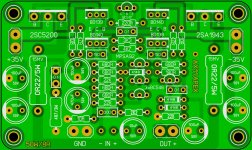
Yes, this is DIY, but before doing any experimenting, i feel one should build according to designed/working sch, and then take experimentation further. one thing that u should first do, is to change all 22k res to 22k and 100u63v to 1000u/16v. you never know, the treasure is hidden in original map (schematic)
Don't forget that the original circuit was using BC639/640, not BD139/140...
Even BD139/140 transistors have big variations (vendor to vendor) so how can you trust a SPICE model?
Miles had mentioned that a certain Toshiba (with Cob around 2pF) was a better improvement over BD139/140. The point is, you can always change the circuit for better or worse...
If you know circuit design, for sure you can improve the "stock" FX8.
Thanks,just an observation.ax11 dual layer
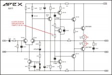
AX11 is an amplifier without servo,we need exactly thermal conditions for the input transistors to keep offset low. Your pcb and other don't take care for this.
There is not much performance gain in using input cap bigger than 10uF (with 22k input resistor), and the high value caps need a lot of pcb space, which is not very practical. Decent quality polarizing elco is just fine for most users especially if you put 100nF non polarizing across it. With ordinary elco you need to know how it should be polarized - if there is DC component coming from source appropriate side of the elco should be oriented towards source. If DC coming from source is negative, negative side of elco should be connected to the source.
If one is using headphone output of CD player as a source, subjective quality of that output (with it's distortions) will influence subjective quality of the sound so much that any comment about sound of AX11 or FX8 will be practically useless.
If one is using headphone output of CD player as a source, subjective quality of that output (with it's distortions) will influence subjective quality of the sound so much that any comment about sound of AX11 or FX8 will be practically useless.
Don't forget that the original circuit was using BC639/640, not BD139/140...
Even BD139/140 transistors have big variations (vendor to vendor) so how can you trust a SPICE model?
Miles had mentioned that a certain Toshiba (with Cob around 2pF) was a better improvement over BD139/140. The point is, you can always change the circuit for better or worse...
If you know circuit design, for sure you can improve the "stock" FX8.
Out of the 3 vendors that mfg'd the BC639/640
Fairchild,On Semi, Philip.
If go with Fairchild, as they where often used in Mil Spec devices. But these are all solid semi companies. So i doubt there much if any variation.
Last edited:
Decent quality polarizing elco is just fine for most users especially if you put 100nF non polarizing across it.
I have all the decent polarized elcos and IMO nothing is as good as BP/NP. If you do an A/B test, of course most will not be able to hear differences...
There is not much performance gain in using input cap bigger than 10uF (with 22k input resistor), and the high value caps need a lot of pcb space, which is not very practical.
Yes. 4.7uF is my minimum standard. The problem is, often we have only 2 options between polarized cap versus 47uF BP/NP. In this case, I have mentioned that the extra capacitance does not hurt.
Of course, smaller footprint is better (for noise/interference). So radial (instead of axial) is preferred, and voltage rating no need too high so the size can be small.
What X is using is BIG 50/100 axial (which I have no experience with, because I have too many better options
), but it looks okay.If DC coming from source is negative, negative side of elco should be connected to the source.
When we design an amplifier, we don't know what the source is, but we assume that there is (output cap) DC protection in the source such that there is zero DC with the source. So the issue is whether the input of the amplifier itself is negative or positive. But DC can come from potentio etc so more common is positive end at the source side.
Out of the 3 vendors that mfg'd the BC639/640
Fairchild,On Semi, Philip.
If go with Fairchild, as they where often used in Mil Spec devices. But these are all solid semi companies. So i doubt there much if any variation.
I was talking about Bd139/140, as I think everybody is using these rather than the original BC639/640. (This is what Egra is using in his simulation)
Are you using FX8 with the original BC639/640? It has good reputation, but specwise, Toshiba low cob parts (I forget the number) are better (and has bigger power rating).
Id be curious if you could figure out what Toshiba cob parts would perform better then the BC639/640 in there perspective positions and be a drop in replacement.
VAS transistor can be replace with lower Cob without any change on the compensation. It will have higher stability, higher slew rate, and lower THD in high frequency (above 1kHz). You even can reduce the compensation. Many friends of mine reported that they can hear the different in a listening test.
2SC3503/2SA1381 is better for VAS, because they have low Cob and high Early Voltage. High Early Voltage can reduce THD at low frequency (below 1kHz).
I need VAS transistor with To-92 package. Power dissipation about 800mW max. Can you suggest me? Of course, it must have low Cob. But I can accept if it do not have high Early Voltage. High slew rate and low THD at high frequency is my priority.
VAS transistor can be replace with lower Cob without any change on the compensation. It will have higher stability, higher slew rate, and lower THD in high frequency (above 1kHz). You even can reduce the compensation. Many friends of mine reported that they can hear the different in a listening test.
2SC3503/2SA1381 is better for VAS, because they have low Cob and high Early Voltage. High Early Voltage can reduce THD at low frequency (below 1kHz).
I need VAS transistor with To-92 package. Power dissipation about 800mW max. Can you suggest me? Of course, it must have low Cob. But I can accept if it do not have high Early Voltage. High slew rate and low THD at high frequency is my priority.
Bimo, can you clarify. Are you saying the 2SC3503/KSC3503 is a drop in replacement for the BC639/BC640, that will also perform better?
The power ratings are much different. Especially considering the FX8 max V is +/-40V.
I was talking about Bd139/140, as I think everybody is using these rather than the original BC639/640. (This is what Egra is using in his simulation)
Are you using FX8 with the original BC639/640? It has good reputation, but specwise, Toshiba low cob parts (I forget the number) are better (and has bigger power rating).
BD139/140 are easy to obtain, inexpensive and easy to compensate them. Some builders are using them in their own VSSA-PeeCeeBee without any Miller capacitor and these amps still running flawlessly (although it depends on the loudspeakers and cables) BDs sound smooth maybe a bit less detailed than some competitors.
Some comments on resistors. I ordered several 1% 0,5W, 0,25W SMD resistors (mostly Panasonic) and most of them have 300ppm TC. I'm not sure it really worth to buy them especially when I compare them to Vishay RN60 or RN65 trough hole series. The latter have nearly same price but have much less ppm (100 or less). I believe that keeping the thermal coefficient as low as possible is more important factor than reducing size and leaving the legs out itself. The question is more complex of course but I'm not sure that SMD resistors sound definitely better than the TH competitors. Does anyone have experience with these? Especially given for APEX amplifiers?
BR
egra
Last edited:
- Home
- Amplifiers
- Solid State
- 100W Ultimate Fidelity Amplifier