In your simulation, 4.7pF capacitor from VAS output back to the IPS inverting input forms what is called Miller input compensation (MIC).
Ye, it is (according Douglas Self's book).
It is depend on the compensation. My simulation did not show an overshoot on 100kHz square wave. Very high slew rate
Ok, I just installed LTspice and can see that there are many mods. All the transistors seem to be different with the "Cordell" designation - is that the person who suggested that transistor?
I also see some very impressive specs typed on the main layout with PSRR at 105dB and 1kHz THD at 30W 0.002% ? If that is so, this is a superb amp.
What are the same specs for the baseline FX8 without the mods?
Next question is, how do I actually run the simulation? I get a message "can't find definition of KSC1845".
Sorry for the beginner at LTspice question...
You should read this: http://www.diyaudio.com/forums/software-tools/260627-installing-using-ltspice-beginner-advanced.html
Please use models that created by Bob Cordell if possible, because those models was proved to be accurate. Then use models that created and listed by Keantoken.
1kHz THD at 30W 0.002% is not superb amp, I have simulate much lower than that
You should look at 20kHz THD at large signal. Some designer does not really care about how much THD, they look at the harmonic profile.Being new to discrete SS class AB, and coming from class D chip amps where 0.1% THD at 40w was considered good - 0.002% is very good to me. Most speakers are no better than -55dB so the amp is not the limiting step for sure. The harmonic content is important though (even order vs odd etc.)
Ok, I am going to have to read up on LTspice.
Ok, I am going to have to read up on LTspice.
More listening with the FX8 with the 51uF input cap mod still continues to sound excellent.
What software and simple hardware rig do folks in SS Forum tend to use to measure amps? In speaker forum it is REW and a sound card. Can REW and a sound card be used to measured THD etc on a dummy resistor load?
What software and simple hardware rig do folks in SS Forum tend to use to measure amps? In speaker forum it is REW and a sound card. Can REW and a sound card be used to measured THD etc on a dummy resistor load?
More listening with the FX8 with the 51uF input cap mod still continues to sound excellent.
What software and simple hardware rig do folks in SS Forum tend to use to measure amps? In speaker forum it is REW and a sound card. Can REW and a sound card be used to measured THD etc on a dummy resistor load?
If there is no DC on signal source (preamp) you can remove input cap.
Hmm...never thought of that before. Right now the "pre-amp" is the headphone output from a CD player - probably safe to say no DC. Easy enough to measure. A "cap bypass" jumper or switch is a convenient way to do this.
I decided to increase the bias current to 150mA (up from 100mA) based on higher current figures used in Bimo's simulation.
I have to say how surprised I am at the beautiful sound quality from such a small and elegant little amp. How much of this sound quality is due to the nice Hitachi lateral FETs? I don't have a scope, but from what others have simulated or measured, what is it about this design that achieves such clean square waves?
Thank you again Apex for a great amp design.
Last edited:
Hmm...never thought of that before. Right now the "pre-amp" is the headphone output from a CD player - probably safe to say no DC. Easy enough to measure. A "cap bypass" jumper or switch is a convenient way to do this.
I decided to increase the bias current to 150mA (up from 100mA) based on higher current figures used in Bimo's simulation.
I have to say how surprised I am at the beautiful sound quality from such a small and elegant little amp. How much of this sound quality is due to the nice Hitachi lateral FETs? I don't have a scope, but from what others have simulated or measured, what is it about this design that achieves such clean square waves?
Thank you again Apex for a great amp design.
It could be interesting for community to have your FX8 moded schematic....
Marc
Line outputs of CD player have output coupling caps - they are safe to be used with DC coupled power amplifier (one without series input cap). Headphone output (usually opamp based) probably has some DC component and is not suitable for DC coupled power amps. No matter how small that DC component is, DC coupled power amp will amplify it and send it to the loudspeakers. You can use your DMM to measure DC component on the headphones output.
It could be interesting for community to have your FX8 moded schematic....
Marc
If there is no DC on signal source (preamp) you can remove input cap.
Check the output offset and how it varies with vol pot setting and how it varies with which Source is connected.Hmm...never thought of that before. Right now the "pre-amp" is the headphone output from a CD player - probably safe to say no DC. Easy enough to measure. A "cap bypass" jumper or switch is a convenient way to do this. ....................
DC coupled amplifiers need lots of protections to save damaging equipment when some innocuous fault occurs.
Ivan is aware
Apex is asleep !Line outputs of CD player have output coupling caps - they are safe to be used with DC coupled power amplifier (one without series input cap). Headphone output (usually opamp based) probably has some DC component and is not suitable for DC coupled power amps. No matter how small that DC component is, DC coupled power amp will amplify it and send it to the loudspeakers. You can use your DMM to measure DC component on the headphones output.
Hmm...never thought of that before. Right now the "pre-amp" is the headphone output from a CD player - probably safe to say no DC. Easy enough to measure. A "cap bypass" jumper or switch is a convenient way to do this.
I decided to increase the bias current to 150mA (up from 100mA) based on higher current figures used in Bimo's simulation.
I have to say how surprised I am at the beautiful sound quality from such a small and elegant little amp. How much of this sound quality is due to the nice Hitachi lateral FETs? I don't have a scope, but from what others have simulated or measured, what is it about this design that achieves such clean square waves?
Thank you again Apex for a great amp design.
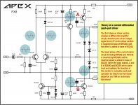
I consider that the push-pull driver stage does the trick mostly. A further step to understand the magic of FX8 (and AX11) see the attached picture.
Attachments
Input signal transformers are usually for balanced to unbalanced.An unbalanced to balanced input signal transformer can also allow removal of input cap.
One uses a Balanced Impedance Source feeding a Balanced Impedance cable into the Balanced Impedance transformer and the output from the transformer feeds an unbalanced Power Amplifier input.
Last edited:
It could be interesting for community to have your FX8 moded schematic....
Marc
+1
Input signal transformers are usually for balanced to unbalanced.
One uses a Balanced Impedance Source feeding a Balanced Impedance cable into the Balanced Impedance transformer and the output from the transformer feeds an unbalanced Power Amplifier input.
I agree. In class D land where I came from, we often use it this way to allow standard RCA unbalanced to drive balanced differential inputs on TPA311x chips to bypass input caps. The resulting lack of input caps and use of differential inputs (vs grounding one of the inputs) really improves the sound quality. I suppose in this case, perhaps the LTP can be configured for differential inputs? This would improve CMRR?
I consider that the push-pull driver stage does the trick mostly. A further step to understand the magic of FX8 (and AX11) see the attached picture.
Thank you for the explanation! Is this significantly different than other push pull class AB amps?
What?... In class D land where I came from, we often use it this way to allow standard RCA unbalanced to drive balanced differential inputs on TPA311x chips to bypass input caps. The resulting lack of input caps and use of differential inputs (vs grounding one of the inputs) really improves the sound quality. I suppose in this case, perhaps the LTP can be configured for differential inputs? This would improve CMRR?
Hi XRK, that "+1" post by RSK with reference to Marc's post was meant for you. You were requested to share your mods on a schematic (preferably).
regards
Prasi
- Home
- Amplifiers
- Solid State
- 100W Ultimate Fidelity Amplifier