Can check connection between [R5, R3, and C6] and [R4, R6, and C8] those were missing in last image you post.
I should also build and check on strip board I have all parts required.
I should also build and check on strip board I have all parts required.
Attachments
Last edited:
Hi Sonal,
Good catch. I had fixed the connection from R5 but missed the one from R6. Unfortunately I just connected it and not the bias is way too high. This circuit doesn't have a pot to adjust that. I'm not sure where to insert that but it looks like it needs it.
Blessings, Terry
Good catch. I had fixed the connection from R5 but missed the one from R6. Unfortunately I just connected it and not the bias is way too high. This circuit doesn't have a pot to adjust that. I'm not sure where to insert that but it looks like it needs it.
Blessings, Terry
Like c08bm said you can use 50R trimpot instead of R16 but D3, D7 and D8 should be on heatsink. Because of your layout other way around will be removing R16 and using trimpot parallel with D3. Just wire timpot to increase resistance when turned CW.
If that's the case, thermal transfer might be a good alternative. Which way on R16 reduces bias? Lower value or higher?
If that's the case, thermal transfer might be a good alternative. Which way on R16 reduces bias? Lower value or higher?
Lower value will decrease bias. I'll suggest remove R16 and and solder resistor with lower value underneath D3. That way you will have better thermal tracking because of forward voltage drop from D7, D8 when temperature rises.
Wow, I typed that from my tablet and didn't notice that it translated "Thermal Trak" to thermal transfer.  With ThermalTrak outputs D7 & D8 would be on the heatsink already. If I can get this working and it sounds good I may try to do a layout for the TT transistors. I'm going to try lowering the bias right now and I will report back.
Blessings, Terry
With ThermalTrak outputs D7 & D8 would be on the heatsink already. If I can get this working and it sounds good I may try to do a layout for the TT transistors. I'm going to try lowering the bias right now and I will report back.Blessings, Terry
OK, I just tried paralleling a 100R pot with R10 and even at it's lowest value, R16 = 0.1R I still have 300mA bias and that is with the light bulb tester in place which is reducing the rails to 7V. Without the light bulb I'm sure I would have blown fuses. Something is not right. Has anyone tried the spice file I made? If I can get that working I will at least have a working circuit to compare to.
Thanks, Terry
Thanks, Terry
Last edited:
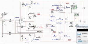
Can you post voltage reading at opamp output, between R3-R5, R4-R6 and voltage across D3, D7, D8.
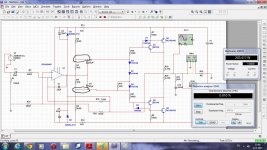
Lots of software were uninstalled for windows 10 upgrade. I better re-install multisim to simulate A4.
I had to pull the IC to get the rails high enough to activate the zeners. I didn't go much higher for fear of burning something. Attached is a marked up schematic
Attachments
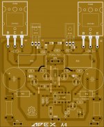
Hi Mr.Juan u can share de sprintlayout files ? because i need to do some change for my needsHello sir here are the files also the reference schematics I use, I did some changes on the layout for my self but you can use the schematic and change some values of the AX-20P to be the original values from AX-20P schematic, I spend a couple of day already checking for error or better say "bugs" and I have not found any more so far, if you guys see any error let me know so I can fix it right away I said this because eyes get tired man
ok here are the files
Regards
Juan
I had to pull the IC to get the rails high enough to activate the zeners. I didn't go much higher for fear of burning something. Attached is a marked up schematic
I would short the anode of D3 with the cathode of D8, to set the output stage to classB. This can be a good intermadiate step to test the basic work of the amplifier.
Sajti
Hi Mr.Juan u can share de sprintlayout files ? because i need to do some change for my needs
Hello sir here is the Sprint file
note: is for Sprint Layout 6 version
Regards
Juan
Attachments
I would short the anode of D3 with the cathode of D8, to set the output stage to classB. This can be a good intermadiate step to test the basic work of the amplifier.
Sajti
Doesn't that just short the VAS?
ThanksHello sir here is the Sprint file
note: is for Sprint Layout 6 version
Regards
Juan
Doesn't that just short the VAS?
No. It short the bias network only.
Sajti
These post will be off topic! I only post here because there are several people here who design or draw PC boards layout.
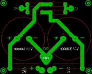
I would need something like the attached power supply board but with 2 pair capacitor and CRC mode.
Also it would be good if I could use MUR860 diodes. No fuse needed on the board..
If someone know similar design on the forum already exist please let me know
Thank you very much
I tried with Sprint 6 and just wasted a couple hours with out any good result.
Greetings
Attachments
- Home
- Amplifiers
- Solid State
- 100W Ultimate Fidelity Amplifier