


That's quite a collection of speakers you have ganged together there.
Nice subwoofer 🙂
Regards
Thanks Mr. Miles for sharing your ax14 amp..
That's quite a collection of speakers you have ganged together there.
Oh yeah.. speaker collection from scrap for my diy...😉

I can't understand those OT reversed .....
It's simple...
Attachments


Last edited:
Why would you do that?
Solid pcb and heatsink connection, no thru hole outputs pins no wraping or broken pins...
Last edited:
A17 CFA
The VAS here is something I've NEVER seen done before, and I find it real interesting.
EDIT: Well, it functions like a Wilson current mirror with large unequal degeneration. But here it's application is very spartan so it wasn't immediately obvious.
Last edited:
Hi,
Here's my AX14TP, A big thanks goes to Juan for all the help without which I wouldn't have been able to do it !!
He sent me all the files (Gerbers) required for me to get the PCB done and also all the emails with pics and such, He's really great ! Unlike others who refuse to help when I request them,He was more than happy to help.
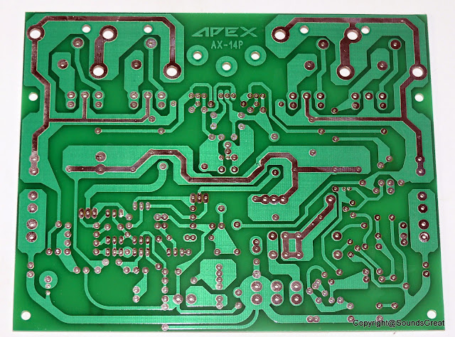
Anyways here's the pics of the PCB ( 70 Microns copper and Glass epoxy) :
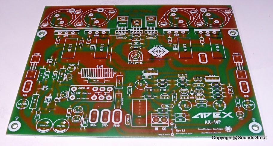

Now the building phenomena begins !! Will post here if I need any help.
Regards.
Here's my AX14TP, A big thanks goes to Juan for all the help without which I wouldn't have been able to do it !!
He sent me all the files (Gerbers) required for me to get the PCB done and also all the emails with pics and such, He's really great ! Unlike others who refuse to help when I request them,He was more than happy to help.
Anyways here's the pics of the PCB ( 70 Microns copper and Glass epoxy) :
Now the building phenomena begins !! Will post here if I need any help.
Regards.
Last edited:
Hi,
Here's my AX14TP, A big thanks goes to Juan for all the help without which I wouldn't have been able to do it !!
He sent me all the files (Gerbers) required for me to get the PCB done and also all the emails with pics and such, He's really great ! Unlike others who refuse to help when I request them,He was more than happy to help.
Anyways here's the pics of the PCB ( 70 Microns copper and Glass epoxy) :
Now the building phenomena begins !! Will post here if I need any help.
Regards.
Nice pcbs,
Regards
oh wow that look really nice man 😀 take your time putting it together that is lovely 🙂
Regards
Juan
Regards
Juan
Hi,
Thanks Mr.Mile,will be posting all the progress here and expect you guidance 🙂!!
All thanks to you my friend,without you this wouldn't have been possible 😉!! Yes will take my time and try to do it right the first time,As they say "Measure twice cut once" in our case "check twice solder once"😀.
One Small doubt,the schematic has different components and the board has different,which one should I follow ? also the input cap value it says 10mfd is that correct ?? cause 10mfd input cap MKP or such will be huge and cannot be accommodated in the given space.
Plus the holes (pitch I guess) and such that you mentioned in the email,has it come out correctly ??
Regards.
Nice pcbs,
Regards
Thanks Mr.Mile,will be posting all the progress here and expect you guidance 🙂!!
oh wow that look really nice man take your time putting it together that is lovely
All thanks to you my friend,without you this wouldn't have been possible 😉!! Yes will take my time and try to do it right the first time,As they say "Measure twice cut once" in our case "check twice solder once"😀.
One Small doubt,the schematic has different components and the board has different,which one should I follow ? also the input cap value it says 10mfd is that correct ?? cause 10mfd input cap MKP or such will be huge and cannot be accommodated in the given space.
Plus the holes (pitch I guess) and such that you mentioned in the email,has it come out correctly ??
Regards.
Last edited:
Yes about the input I did use 10uF electrolytic and is fine with me, the maximum distance from lead to lead is 15 mm but can accommodated different sizes too. also the input cap you don't need a really large one the the maximum input signal is not going to be more than 1V example CD player, MP3's, iPods etc I mean is up to you what ever make you happy go for it 🙂
the maximum size cap the rectangular ones is about 21 mm x 10 mm
Regards
Juan
the maximum size cap the rectangular ones is about 21 mm x 10 mm
Regards
Juan
Attachments


Hi,
Thanks Juan for the reply,But what about the components ?? which should I use the one's on the board or the schematic ??
Well if you use the normal box caps (WIMA Etc),I guess its okay but I want to use as mentioned in the previous post the MKP or MKt type caps like this one below which surely wouldn't fit.
Regards.
Thanks Juan for the reply,But what about the components ?? which should I use the one's on the board or the schematic ??
Well if you use the normal box caps (WIMA Etc),I guess its okay but I want to use as mentioned in the previous post the MKP or MKt type caps like this one below which surely wouldn't fit.
An externally hosted image should be here but it was not working when we last tested it.
Regards.
Last edited:
Ax-14 stereo done. Next A-17...., thanks to Mr. Mile for schematic & john bali for ax-20 layout(litle modified).
An externally hosted image should be here but it was not working when we last tested it.
- Home
- Amplifiers
- Solid State
- 100W Ultimate Fidelity Amplifier