Provided the current source Q7 drives 15 mA thenIf the cap had 15V, this would mean that all the bias current goes into the string of predriver transistors, with nothing left for Q2.
It would be a hard-switching class B.
at the collector of Q7 the voltage must be -15 v and at the base of Q5 the voltage is 0 v.
With this clamp already proposed by Hugh the thd is down to 0.3% at 15 v in 1 kHz
It can be reduced further but depends on property of power BJT.
The odd harmonics are one order of magnitude lower than the even. I guess that sounds good.
It can be reduced further but depends on property of power BJT.
The odd harmonics are one order of magnitude lower than the even. I guess that sounds good.
Attachments
Last edited:
Hi Hahfran,
Yes, generally my experience too. The best profile, according to Jean Hiraga twenty years ago, is the monotonic decreasing profile, where successive harmonic peaks form a straight line down to about -140dB.
BTW, is Q6 in your schemat NPN (it may be an error?)
Hugh
The odd harmonics are one order of magnitude lower than the even. I guess that sounds good.
Yes, generally my experience too. The best profile, according to Jean Hiraga twenty years ago, is the monotonic decreasing profile, where successive harmonic peaks form a straight line down to about -140dB.
BTW, is Q6 in your schemat NPN (it may be an error?)
Hugh
Not quite...I've been testing the reliability of LTSpice fourier computation and the schematic shown was such a test....thd significantly improved over the correct circuit...
at least according to Spice ...
Yes Hiraga's rule has been confirmed in numerous listening tests.
at least according to Spice ...
Yes Hiraga's rule has been confirmed in numerous listening tests.
Hahfran,
For Q6 to pass a current into Q7's base, its base must be 0.6V lower than its emitter, not higher, and since the 68R resistor is connected to the emitter of the output device Q7, no base current can flow. If LTSpice is working with this connection, there is a bug.....
I really think Q6 should be a 2N5551 (and in fact I'd change it to a beefier device like a 2SC4793, MJE340 or MJE15030).
To properly simulate the outsized BE junction on Q7, diode D2 might be something capable of 1A. I was never sure about the cap; 12nF seems about right.
Cheers,
Hugh
Hahfran,
For Q6 to pass a current into Q7's base, its base must be 0.6V lower than its emitter, not higher, and since the 68R resistor is connected to the emitter of the output device Q7, no base current can flow. If LTSpice is working with this connection, there is a bug.....
I really think Q6 should be a 2N5551 (and in fact I'd change it to a beefier device like a 2SC4793, MJE340 or MJE15030).
To properly simulate the outsized BE junction on Q7, diode D2 might be something capable of 1A. I was never sure about the cap; 12nF seems about right.
Cheers,
Hugh
Yes there is a bug... LTSpice does the dc setup perfectly and continues with the harmonics analysis. I have been using LTSPice "certified" models to be sure there is no .model error.
PSpice does not find a dc operating point.
I had been working on theory of semiconductors once and hence am very wary of dynamic simulations...one should always have a nice piece of artwork
for ex. a decorated flask filled with enough grains of salt on the desk when
working with sims....
Some/most sims (not sure about LTspice) do small-signal ac analysis (which includes harmonic analysis IIRC) around a linearized bias point (that's why it is called small-signal analysis). This often works even with the DC conditions way wrong. I wouldn't call it a bug, it's the nature of the beast.
jd
Yes the sims can hardly do more, in terms of large signal ac analysis. Large signal would work well with triodes where i_anode= const*Vgc^3/2 is a sound approximation ( except for the small range where i_anode is almost 0) ...alas those semiconductors are somehow
"quantum-mechanical"... electron states .... quantum wells ..non linear differential equations...none of that applies to tubes ..but could tubes operate in the vicinity of black holes or will all those electrons get sucked up by the black hole before they reach the plate? Fortunately none of those questions are valid if it is about a Keith Jarret solo concert these are the fundamental things
"quantum-mechanical"... electron states .... quantum wells ..non linear differential equations...none of that applies to tubes ..but could tubes operate in the vicinity of black holes or will all those electrons get sucked up by the black hole before they reach the plate? Fortunately none of those questions are valid if it is about a Keith Jarret solo concert these are the fundamental things
With this clamp already proposed by Hugh the thd is down to 0.3% at 15 v in 1 kHz
It can be reduced further but depends on property of power BJT.
The odd harmonics are one order of magnitude lower than the even. I guess that sounds good.
I arrive at a much lower distortion figure under steady state conditions.
But you have to take care that the circuit has effectively reached its steady state before you make the measurement.
What I do is to run the circuit for a very long time (1s) with the intended signal level, and then, I look at final voltage across the cap and include .ic statements forcing that voltage at the next run.
If you rely on a .op, it wont work, because the bias level is dependent on the dynamic operating conditions.
With 15Vpk, the distortion is under 0.02%, almost pure 2nd harmonic.
But the circuit has a sweet spot regarding the source resistance: with 15K at the input, the figure is down to 0.003%.
Note that on your schematic, the cap value is 0.22 farad.
BTW, simulations are no evil, you have to understand what is going on and make sure it follows exactly the path you intend.
They are simply a tool, useful but dumb, and relying too much on default settings may give incoherent results. You have to make yourself the critical decisions.
AKSA,
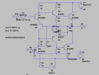
Q6 cannot be a NPN: this would make the positive half-side inverting, and it would conflict with the non-inverting negative side.
The topology is in fact a circlotron with PNP composites at the output, and the Rush cascode as the phase shifter.
Yes I have been testing the simulation under various aspects...I am a retired mathematician and my first response is always I don't believe any program unless I know what is actually programmed....
Indeed the source resistance has ( and should have) an effect but I did not see any effect of the value of the cap in terms of "steady state".
I have now redesigned a bit such that emitter and collector resistors resp. are inserted from which the feedback is taken via 100 Ohms resistors each but haven't found out how to simulate iq thermal stability.
Elvee,
You are right; however, the device is incorrectly drawn because it is inverted; emitter should be to the upper, 10R resistor, while collector should be to the base of the npn output and the 68R.
Hugh
Q6 cannot be a NPN: this would make the positive half-side inverting, and it would conflict with the non-inverting negative side.
The topology is in fact a circlotron with PNP composites at the output, and the Rush cascode as the phase shifter.
You are right; however, the device is incorrectly drawn because it is inverted; emitter should be to the upper, 10R resistor, while collector should be to the base of the npn output and the 68R.
Hugh
Yes I have been testing the simulation under various aspects...I am a retired mathematician and my first response is always I don't believe any program unless I know what is actually programmed....
Indeed the source resistance has ( and should have) an effect but I did not see any effect of the value of the cap in terms of "steady state".
I have now redesigned a bit such that emitter and collector resistors resp. are inserted from which the feedback is taken via 100 Ohms resistors each but haven't found out how to simulate iq thermal stability.
You have to use "temp" as a source for DC sweep simulation: see example
Attachments
I arrive at a much lower distortion figure under steady state conditions.
But you have to take care that the circuit has effectively reached its steady state before you make the measurement.
What I do is to run the circuit for a very long time (1s) with the intended signal level, and then, I look at final voltage across the cap and include .ic statements forcing that voltage at the next run.
If you rely on a .op, it wont work, because the bias level is dependent on the dynamic operating conditions.
With 15Vpk, the distortion is under 0.02%, almost pure 2nd harmonic.
But the circuit has a sweet spot regarding the source resistance: with 15K at the input, the figure is down to 0.003%.
Note that on your schematic, the cap value is 0.22 farad.
Elvee
I could not confirm this distortion level. To which schematic does it refer?
Nevertheless it appears the max output for about 1% thd is limited to about 17 volts. The QUAD 303 triple cascade goes as far 25 V and appears to show no switching, too.
Elvee
I could not confirm this distortion level. To which schematic does it refer?
Nevertheless it appears the max output for about 1% thd is limited to about 17 volts. The QUAD 303 triple cascade goes as far 25 V and appears to show no switching, too.
You can use this one without any modification: the .ic is OK for 15V.
Attachments
Ok. Thanx for your help. I see now why we disagree...I do pencil and paper and assume hence the amp is powered on ...LTSpice doesn't. To simulate one has to start the sine about 1 sec delayed and perform transient analysis "triggered". This doesn't seem to work except with your method of line commands. Apparently the Tdelay parameter applies to DC offset, too. Using your simulation of triggering .tran I find indeed at 20 V a wonderful harmonics spectrum. max out for thd 1% is now a matter of the values of the Baxandall clamp and to a lesser extend the value of the cap. For large signal performance analysis LTSpice doesn't care about transistor models.
Last edited:
Ok. Up to 23 V input the harmonics spectrum remains simply nice... at 25 V thd is 0.154239% but 3rd h is higher than h2.
This looks like a wonderful candidate to qualify for active speaker project as that won't require SOAR protection and not even simple current protection as there are no passive crossovers ... the impedances are all well known thus that it is a matter of selecting a power BJT thus that for minimum impedance / max phase shift SOAR is wide enough.
This looks like a wonderful candidate to qualify for active speaker project as that won't require SOAR protection and not even simple current protection as there are no passive crossovers ... the impedances are all well known thus that it is a matter of selecting a power BJT thus that for minimum impedance / max phase shift SOAR is wide enough.
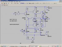
Ok attached the redesigned Vish R12 throu R15 being added, providing some Iq thermal
stability . It can be demonstrated in the sim by adding current sources to simulate increased Iq. Also extending R14 R15 with a parallel RC compensation is possible if necessary. Using 2SC2922 for Q5,Q7 gives a sufficient SOAR margin.
stability . It can be demonstrated in the sim by adding current sources to simulate increased Iq. Also extending R14 R15 with a parallel RC compensation is possible if necessary. Using 2SC2922 for Q5,Q7 gives a sufficient SOAR margin.
Attachments
Thermal stability is not an issue: under no signal conditions, Iq is about 10mA (see #113 above), and doesn't vary much with temperature.
The current increases to over 2A under large signal conditions, but this is a "feature" of the circuit, and has nothing to do with temperature.
It is a sort of "sliding class" amplifier, but the reaction delay makes it awkward.
The current increases to over 2A under large signal conditions, but this is a "feature" of the circuit, and has nothing to do with temperature.
It is a sort of "sliding class" amplifier, but the reaction delay makes it awkward.
Thermal stability is not an issue: under no signal conditions, Iq is about 10mA (see #113 above), and doesn't vary much with temperature.
The current increases to over 2A under large signal conditions, but this is a "feature" of the circuit, and has nothing to do with temperature.
It is a sort of "sliding class" amplifier, but the reaction delay makes it awkward.
There is no reaction delay I have explained that post 2084110.
Of course junction temperature is an issue. It is always an issue because of the e^kT dependency. This class B reaches max dissipation at about 2/3 of max power. Since "heat" does not flow, but diffuses it takes some time to cool the junction down. So if after a few milliseconds of max dissipation, there is a silent passage, the Iq will be pretty much higher well above 100 mA if I assume the junction temp is about 100 °C . That can lead to uncontrolled thermal runaway. And very often does.
Even if not, the operating point is not constant. This may or may not be an issue in terms of sonic quality but anyway such does neither appear in class A nor in class B tube amps.
- Status
- This old topic is closed. If you want to reopen this topic, contact a moderator using the "Report Post" button.
- Home
- Amplifiers
- Solid State
- Class B w/o crossover distortion (1975)