But that refers to near class A...Vish is class B iq is <10mA.
Very interesting is that a simple not optimized current dumping circuit has a harmonics spectrum independent of reactive load and frequency. The harmonics spectrum is poor but
it doesn't depend on the impedance (f) . Since an error feedforward/ feedback combination is difficult to optimize I am going to find out a principal difference of current/voltage feedback and of emitter grounded/ emitter follower power stage.
Sims allow only a very rough estimate in terms of reactive distortion.
Linear class A crossing Iq would be around 2A. I1 + I2 would total 2A at all times.
More like 4A if we are talking about a 4ohm load. Yours was designed for 4 was it?
So what is Iq 600mA? I don't think of that as true Class A. But also never goes B.
Maybe Hyperbolic A is my class? I'm not sure what effect that has upon stability?
But there are certainly deliberate complimentary non-linearities you won't find in
pure A or B. And my AB crossing (if thats indeed what it is) is rail-to-rail wide...
I hear amps with 2% distortion sound great. And amps with unmeasureable THD
sound terrible. Thats not to say distortion is good. But perhaps how gracefully
an amplifier responds and recovers when asked to follow or drive the impossible,
that makes all the difference. It is not distortions of simple non-linearity that
annoy our listening the most.
Does non-linearity prevent my sim from misbehaving into reactive loads?
The phase margin is not so good, I wasn't expecting a favorable result.
So I am a little surprised to find it was tolerant of such abuse. Such
margins are computed only for small signals in the quiescent state???
Last edited:
I am not sure what the reasons are but I have been testing a commercial very fast MOSFET amp with good reputation but my ears were right...it is also quite sensitive to reactive loads I have always suspected there is distortion >3khz ( the crossover to the tweeter) and it is. A bunch of high harmonics.
They are computed for the initial conditions of the circuit, including the voltage sources.Such
margins are computed only for small signals in the quiescent state???
Which means in general the quiescent state, but not necessarily: if, for example, the input is a square wave starting at +1V, the Bode plot will be calculated for that very level (supposed to have existed an infinite time before the simulation proper is started).
One largely unobserved measure of sonic quality is the frequency dependency of damping.
Simulation yields entirely wrong results compared to measuring real amps.
I found it impossible to compensate the Vish amp to yield a constant damping over frequency this could be due to voltage feedback. Voltage feedback ( as analysis of small signals according to 4 pole theory yields) reduces the output resistance and hence increases theoretically damping but this does not appear to be valid for large signals.
Voltage feedback ( as analysis of small signals according to 4 pole theory yields) reduces the output resistance and hence increases theoretically damping but this does not appear to be valid for large signals.
It work for large signals, but if you use negative feedback,
for the damping factor to be constant vs frequency, your amp
need to have a constant open loop gain in the relevant bandwith,
so the negative feedback will stay constant through this frequency range..
Yes yes...BUT open loop gain is calculated with complex 4 pole parameters not taking into account that these are not valid for large signals. This could be the reason why simulations yield false results. This can be checked easily just short the SINE souce amplitude=0 ser res.=0 and put a sine source at the output also Rser=0 and feed the output via a 8 ohms resistor. Yo don't see the dependency of damping on frequency but you can measure it on a real amp. What sims yield however is some sort of hunch which topologies could do better.
Some results : amongst tested in sim the common emitter QUAD triple cascade clearly outperforms the simpler emitter follower cascade in terms of damping however SPICE cannot perform a reliable frequency analysis of damping.
Very amazingly I found that a error forward topology when optimized for thd is extremely poor in damping BUT depending on error takeoff it can be optimized for damping.
This is interesting and to my knowledge has not been discussed. Btw error feedforward must not necessarily be implemented as current dumping.
Well, it work, at least in my simulator..
Here two graphs displaying the behaviour of a symetrical differential amp.
One is the output impedance measured using small signal analysis.
The second one is a simulation at 1khz and 20khz in large signal.
That seems to correlate what is displayed in the small signal
analysis, i.e; an output impedance ratio of about 4 between the two
frequencies..
Attachments
Concluding remark on Vish:
the Vish topology provides a wonderfully descending , even fine-tuneable, spectrum of harmonics- as long as it doesn't drive complex loads and as long one doesn't demand too much power. Given this conditions it sounds better than any class A I have listened to.
Its Achilles heel is the "lower" transistor of the Rush, in combination with voltage feedback.
The sensitivity to complex loads can be avoided to some degree by adding emitter resistors and taking feedback from these.
But his does not help very much. Once the Vcb of the lower Rush drops to zero the transistor gets saturated and all distortion is produced from this effect as its gain drops to 1. With much faster power transistors than the single-diffused 2N3055 the amp then gets stuck to a rail and does not recover i.e.keeps latched up. This happens always at drive input above 25 Volts p in order to get 39 Watts into 8 Ohms even if the amp is redesigned to drive mainly inductive loads.
It is a pity because in most cases one has power in terms of milliwatts to a few watts and then this amp is unbeatable in sonic quality.
But in real programs one has to consider dynamic headroom of up to 70 dB and unfortunately this amp cannot handle this dynamic.
It can also not handle crest factors of about 2 present on direct cut LPs.
So alas.... not suitable as an amp for active speakers.
I chose a slightly modified version of the QUAD 303 triple cascade which features also a
Rush cascode but with current feedback to the emitters.
This has bey far not he wonderful spectrum of harmonics but is very standfast against overdrive and is very tolerant versus reactive loads.
Concluding remark on Vish:
the Vish topology provides a wonderfully descending , even fine-tuneable, spectrum of harmonics- as long as it doesn't drive complex loads and as long one doesn't demand too much power. Given this conditions it sounds better than any class A I have listened to.
Its Achilles heel is the "lower" transistor of the Rush, in combination with voltage feedback.
The sensitivity to complex loads can be avoided to some degree by adding emitter resistors and taking feedback from these.
But his does not help very much. Once the Vcb of the lower Rush drops to zero the transistor gets saturated and all distortion is produced from this effect as its gain drops to 1. With much faster power transistors than the single-diffused 2N3055 the amp then gets stuck to a rail and does not recover i.e.keeps latched up. This happens always at drive input above 25 Volts p in order to get 39 Watts into 8 Ohms even if the amp is redesigned to drive mainly inductive loads.
It is a pity because in most cases one has power in terms of milliwatts to a few watts and then this amp is unbeatable in sonic quality.
How many watts?
Do you have any measure?
I have a bunch of measures but the demo version of the spectrum analyzer has no store option... but I can tell you that for power up to 20 Watts into a 7" speaker ( SEAS Excel in closed dampened box) the thd is < 0.03% with h2 > h3, h2>h4, h4 >>h5. h6 etc is not measurable. At about 22 watts the thd jumps to >30% and the amps goes in latchup mode at slightly higher input levels. For frequency from 60 to 100 hz the impedance is real and thd is then also 3% to 6% - the amp is compensated for inductive load.
It is a shame! I couldn't believe what I hear ...wonderful wonderful music. The distortion at the resonant frequency is not that disturbing. But 20 watts is not enough given the
efficiency of the speakers.
It is a shame! I couldn't believe what I hear ...wonderful wonderful music. The distortion at the resonant frequency is not that disturbing. But 20 watts is not enough given the
efficiency of the speakers.
Last edited:
I have a bunch of measures but the demo version of the spectrum analyzer has no store option... but I can tell you that for power up to 20 Watts into a 7" speaker ( SEAS Excel in closed dampened box) the thd is < 0.03% with h2 > h3, h2>h4, h4 >>h5. h6 etc is not measurable. At about 22 watts the thd jumps to >30% and the amps goes in latchup mode at slightly higher input levels.
But 20W is more than enough for me
")
Which is the exact circuit that you built (I saw many simulated by Elvee)?
Do you think that it can be biased entirely in class A?
PS: if you like it so much, you could think to build more efficient speakers
I made a couple of modifications so I will post the last version later. However what could one do with an amp that latches up before it clips? You got to have a bipolar dc detector
that cuts off the speaker and the power supply in case of latch-up.
No it is class B but the power devices are never cut off the minimum iq of about 10 mA is perfectly maintained in the device which were not conducting in class B. I think the perfect harmonics spectrum cannot be easily achieved with a complimentary class A.
No I make speakers by design of the case those I cannot buy...otherwise I would just buy.
Last edited:
Thanks for the analysis, Hahfran. You really went to town on this topology. The monotonic decreasing spectrum caught my eye too, as I reasoned it would sound absolutely stunning, but I've been working on other topologies which give similar profile but which handle reactive loads. You have one of them in your schematics selection!
Hugh
Hugh
I haven't read every post here, but this sounds like an interesting idea. If I understand it right, low output stage dissipation like class B but passable distortion levels. Could be useful for cheap power for outdoor, garage speakers, or background music wherever... Is there a semi-final schematic?
The last word on Vish topology
Attached final schematic. Resistors R5 thru R10, R13,R15 C2 are for fine tuning the harmonics spectrum. A truly wonderful descending spectrum was achieved.
Resistors R 6 throu R9, C4, R17, R18 reduce the sensitivity to reactive load.
Power is limited by Vce of Q3 to about 25 Watts into 6 ohms. More power can only be achieved with lower load impedances.
With the rather fast transistors the amp tends to latch up before it clips. The latching appears when Vcb of Q3 drops to zero. It can most possibly be avoided with slower
transistors for ex. instead of 2SC5200 the epibase BD249C. This however won't help
if Q4 and Q6 are about ft=20 mHz ( the 2SA1112 is specified ft=200 mHz) but such types are rare in combination with high hfe ( 200 up).
This amp calls for engineering because its sonic quality is superb this is due to the harmonics spectrum and absence of crossover distortion. I am convinced it outdoes
Hiraga class A - and it is class B! the quiescent current is very stable at 15 mA.
It is also dynamically constant this may be a key as the same thermal conditions apply to the junctions of BJTs of class A amps.
Some hints: Q1 Q2 Q3 must NOT be in thermal contact with heatsink.
Diode D1 is crucial for fine tuning best choice is a very fast diode with very low
variation of Vd/if . A foil capacitor parallel reduces odd harmonics further.
A Shottky sharply rises odd harmonics.
Capacitors C1 C6 C7 are bipolars paralleled with a foil capacitor - these three devices account for 50% of the devices' total price.
Q5 Q7 R17 R18 L1 R20 are not on PCB R17 R18 are induction free types they come in SOT 220 package and must be mounted on heatsink.
Thus there are no fat currents anywhere flowing on the PCB.
The amp must be driven by a preamp that can deliver up to 25 volts p however the input current is around 200 microamps ac.
Attachments
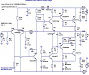
I tried some modifications to the Visch Class-B stage in LTSpice.
1) Changed the topology of the upper O/P transistor to emitter-ballasted (a la Naim NAP-140).
2) Changed the topology of the lower O/P transistor to collector-ballasted (a la Naim).
3) Removed the additional negative voltage rail - I kludged it by adding one additional diode drop with a resistor in parallel - it seems to work, but may need further modification.
4) Added Baxendall diode and capacitor to emitter of lower driver, connected to collector of lower O/P transistor.
These changes make it better behaved at high swings (close to clipping), without losing much of its excellent sonics at low swings and crossover. I don't fully understand how either the original circuit or the modified circuit actually works, but it nevertheless does seem to work rather well...
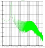
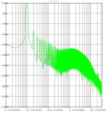
The rest of the circuit is just a minimal LTP and VAS - lots of elaborations can be tried here, but it's pretty good as it is. The THD20 FFT in the middle is at ~14V output amplitude into 8 ohms, while the one on the right is for ~28V amplitude into 8 ohms. In both cases, H2 dominates - exceptionally so at lower amplitudes.
1) Changed the topology of the upper O/P transistor to emitter-ballasted (a la Naim NAP-140).
2) Changed the topology of the lower O/P transistor to collector-ballasted (a la Naim).
3) Removed the additional negative voltage rail - I kludged it by adding one additional diode drop with a resistor in parallel - it seems to work, but may need further modification.
4) Added Baxendall diode and capacitor to emitter of lower driver, connected to collector of lower O/P transistor.
These changes make it better behaved at high swings (close to clipping), without losing much of its excellent sonics at low swings and crossover. I don't fully understand how either the original circuit or the modified circuit actually works, but it nevertheless does seem to work rather well...
The rest of the circuit is just a minimal LTP and VAS - lots of elaborations can be tried here, but it's pretty good as it is. The THD20 FFT in the middle is at ~14V output amplitude into 8 ohms, while the one on the right is for ~28V amplitude into 8 ohms. In both cases, H2 dominates - exceptionally so at lower amplitudes.
Attachments
- Status
- This old topic is closed. If you want to reopen this topic, contact a moderator using the "Report Post" button.
- Home
- Amplifiers
- Solid State
- Class B w/o crossover distortion (1975)