Great Alexandre (soundbuster)...take care of my threads while i'm out
Thank you....we have Greg that will take care too.
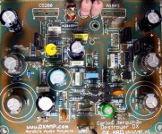
There's a picture from the HRII in this video....shows board assembled clearly:
YouTube - Dx Corporation, excellence in audio amplifiers!
regards,
Carlos
Thank you....we have Greg that will take care too.
There's a picture from the HRII in this video....shows board assembled clearly:
YouTube - Dx Corporation, excellence in audio amplifiers!
regards,
Carlos
Attachments
Last edited:
Bias set up
All,
I have followed the steps on Greg's site for bias adjustment (linked a few posts up). I have 10 Ohm/10 Watt resistors in place of fuses. I powered up to mains voltage with a variac and, so far, so good, no smoke. The rail voltages come up as expected +/- 35V
The problem is I am only getting about 80-200 mV across the protection resistors. That is, no where near the suggested 800 to 1100 mV. It seems not to change much when I adjust the bias potentiometer.
a) what is the expected range in voltage across the resistors variation of the potentiometer
b) Any suggestions as to what might be wrong?
I haven't check the second channel yet as it is late and I am tired. I wanted to put this question out there in hopes that I can return to it tomorrow with some ideas and a fresh set of eyes.
Thanks for any advice you might have.
Ryan
If bias controls is not adjusting, then the most probable mistake is
in this same circuit...check the position you assembled the transistor into the board, also the resistances you have around this same circuit...check also the position of insertion in the board to the drivers too...people use to confuse these BD139, maybe U2 or not... i use to make mistakes...do not know about you.
If your range of adjustment is not fine, then increase the resistance (total) or your trimpot value from base to emitter.
This transistor, when you watch the metal blade, with leads pointing down, then from the left to the rigth you have base, colector and emitter.... sometimes screw crossing it produces a short from colector to the heatsink that may be grounded... take care about that, measuring continuity, or resistance, from the heatsink to the colector..cannot have a short there.
I will be out for a day, visiting doctors, so, you may not find me..but post everything you need and soon i will be back to give you a hand.
Check voltage drop into the rail voltage regulators (BD139/140).... check if you are having some volts drop there.
good luck,
regards,
Carllos
same result, other channel
I applied the same process to the other channel and have similarly 100 mV across the 10R protection resistors. And again, no variation in that when I turn the trim pot.
I will examine the bias circuit to make sure that I have not wired it incorrectly.
I was comparing the Nicco board/parts (that is what I am building from) with those posted on Greg's site. VR-1 on Greg's site is 100R. The parts that Nicco supplied had this (R30) as 1K ohm. I did rotate the pot quite a number of turns and did not see any change in the bias. Still is it possible that I didn't vary the potentiometer enough?
Thanks for the help.
Ryan
The trimpot installed into the circuit give you strange readings
remove it and test it outside the circuit.
This transistor may be inverted....BD139, with metal facing you and leads point down, left to rigth you have Base, Colector and Emitter.
Check these connections and the resistances you have associated to this circuit.
regards,
Carlos
remove it and test it outside the circuit.
This transistor may be inverted....BD139, with metal facing you and leads point down, left to rigth you have Base, Colector and Emitter.
Check these connections and the resistances you have associated to this circuit.
regards,
Carlos
Thank you Carlos
I will check as you suggest.
On his website with pictures of his HR II assembly, Salesmonster indicates that one should measure 3k Ohms between the leads of the bias adjust circuit. That is where I set mine originally, before I soldered servo+ and servo- to the main PCB.
Thanks again,
Ryan
I will check as you suggest.
On his website with pictures of his HR II assembly, Salesmonster indicates that one should measure 3k Ohms between the leads of the bias adjust circuit. That is where I set mine originally, before I soldered servo+ and servo- to the main PCB.
Thanks again,
Ryan
Yep... this works with the majority of amplifiers, but there are some
variations... this start up setting does not work for all amplifiers.
You may have mistakes when building, this happens a lot, in more than 40 percent of people....so, you must check carefully, each part, if correct the value and position, check solders, check if the correct transistor in the correct lead position is inserted...well....i do not know about you, but i usually make mistakes....i have build thousands amplifiers..but this does not made me better, i continue to assemble things inverted.
Your bias not adjusting seems you have errors, at least one!
regards,
Carlos
The reality, dear fellows, is that we have some confusion
Here you have the HDII group buy..this was the first confusion, the amplifier is High Resolution II and Nordic have openned a HDII group buy.
The second confusion is that he made the board, and part numbers are from his schematic... we have the first schematic at Greg's site.
I cannot remember anymore, i have some troubles about memory now a days, but the HDII thread may help you to find solution... so, you have to study all informations available... even the Dx amplifier thread has something there too.
Here is the link, please read it entirelly:
http://www.diyaudio.com/forums/group-buys/108456-destroyer-x-amplifier-dx-hdii-version.html
I will search for Nordic's schematic to post it here.... sadly he disappeared, it seems he passed away, as he was very sick about nervous connection from brain to body.
regards,
Carlos
Attachments
Here you have Nordic's schematic
I really suggest you to go to the Dx Blame ST, because performance is sligthly better and we all remember things about it to help....the Blame was made some monthes ago and the HRII was made years ago.... the HRII group buy to boards was made several years ago, and we have running group buy to the Blame.
regards,
Carlos
Attachments
Thank you
Carlos for the support. I will find my error at some point. I agree, I will build the Blame next (for me") ). I have the gorgeous red boards from Rudi. This project is for a friend as a gift. If I like the Blame even better, I will build an upgrade for my friend.
). I have the gorgeous red boards from Rudi. This project is for a friend as a gift. If I like the Blame even better, I will build an upgrade for my friend.
I have taken a cold so I won't be able to stare at things for a bit. But I will find the mistake. I may post some pictures of my boards here to take advantage of more pairs of eyes.
Thanks again,
Ryan
Carlos for the support. I will find my error at some point. I agree, I will build the Blame next (for me
). I have the gorgeous red boards from Rudi. This project is for a friend as a gift. If I like the Blame even better, I will build an upgrade for my friend.I have taken a cold so I won't be able to stare at things for a bit. But I will find the mistake. I may post some pictures of my boards here to take advantage of more pairs of eyes.
Thanks again,
Ryan
Further tests...
I looked at my boards against the schematic a few times and all seems well. So I decided to hook up the board to a bench power supply. The power supply can put out +/- 70 volts and a lot of current (I used a transformer from a dyanco 400 for this power supply). I run it from a variac to set it to output lower voltages.
1. I connected the power supply + lead to 10R 10W resistor, then from the 10R resistor to V+ on the hrII board.
2. Similarly I connected the power supply - lead to 10R 10W resistor, then from 10R to V- on the hrII board
3. I connected voltmeters across each of the 10 ohm resistors
Now, as I raise the power supply voltage, the voltage across the resistors goes high, probably too high e.g. 6-7 volts. I stopped the Power supply at about 22 Volts as the 10R resistors were getting a bit warm by now.
When the supply voltage was at approximately 20+ volts (6+ volts across 10R), I tried to adjust the bias at the servo trim pot and nothing happened to the voltage across the protection resistors...I only observed small variations in either direction of the trim pot.
It seems clear that the power supply I have in the chassis I plan to use has problems.
But now I am uncertain how to proceed with the bias adjustment. Are voltages that high expected across protection resistors when you begin to dial in the bias setting?
What am I missing here?
Thanks for your help.
Ryan
I have check for shorts between all the pins on the devices connected to the heat sink, there are no shorts there.
Last edited:
Bias not operating seems you have errors in the bias circuit
or errors in the circuit board.
Check the bias circuit till you find something wrong... the screw that fix the transistor to the heatsink sometimes produces short from the this transistor's colector to the heatsink, and the heatsinks should be grounded..this means short to ground... when you have no adjustment, seems the bias circuit or something in the associated circuit is wrong.
This is normal, happens with the majority of people, mistakes are common and very human.... we can see hundred times an inverted transistor without detect it, sometimes we have BD139 in a place we should have BD140, also happens with the small ones..sometimes people put the NPN output in the place destinated to the PNP output.
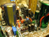
I cannot see with your picture, has not the needed quality of ligth, focus and angle..but i could see you're using a coil with a ferrite inside...remove that ferrite as soon as you can, it saturates and produces a "tac!" noise when you have high current crossing it...exactly when the bass comes strong.
Check everything once again....make a print copy of your schematic, put your board against ligth and check each copper track painting in your schematic in red..check each transistor soldered watching the model, if PNP or NPN and the position of Base, Colector and Emitter...check each capacitor and go painting this in the schematic copy till you cover the copy entirelly with red lines.
Check your supply voltage polarity, check if you're sending positive to the positive side.
Check solders and if you have shorted joints, use magnified glass (lenses)
I would like to be at your side my dear, to inspect this over your shoulder, but i cannot, so, you will be the one to check each part.
Also check each resistance value, you can measure it in the circuit and lift one side (dessolder) to check it if the value measure seems suspectious to you...the resistance value can be smaller because the circuit, but cannot be higher..this is the clue to lift one side to measure.
Also you can check resistances.... disconnect supply wires and measure from positive to ground (the board positive input), also negative to ground and also positive to negative..... INVERT your probe point tips and no measurement should me smaller than 30K.... it is usually around 500K or even more....but be patient, as your condenser will charge and the meter will have overflow..you should wait or remove all rail condenser from the board...if you have shorts...that's your problem and you may search for the part shorted..usually semiconductors does that.
Bias trimpot MUST operate, so, you have to read huge differences in voltage when you turn it, unless you have errors in the bias circuit, in the associated parts or in your circuit board.... there's no cake recipe to find the bug...there's hard work to check with patience.... each symptom can have many possible causes.. so, i am not able to point you the part missed, wrong or damaged.
Base to emitter voltage helps a lot...it should be from 550 to 640 milivolts.... also if you have not voltage from base to emitter, or colector to emitter..seems you have a shorted (burned) transistor.
Here you have the "method" to adjust amplifiers, you can see the bias trimpot operation..not your amplifier, this is to the blame..but the way we do is the same:
http://www.youtube.com/watch?v=Ku-w-WAxHs8&feature=related
regards,
Carlos
or errors in the circuit board.
Check the bias circuit till you find something wrong... the screw that fix the transistor to the heatsink sometimes produces short from the this transistor's colector to the heatsink, and the heatsinks should be grounded..this means short to ground... when you have no adjustment, seems the bias circuit or something in the associated circuit is wrong.
This is normal, happens with the majority of people, mistakes are common and very human.... we can see hundred times an inverted transistor without detect it, sometimes we have BD139 in a place we should have BD140, also happens with the small ones..sometimes people put the NPN output in the place destinated to the PNP output.
I cannot see with your picture, has not the needed quality of ligth, focus and angle..but i could see you're using a coil with a ferrite inside...remove that ferrite as soon as you can, it saturates and produces a "tac!" noise when you have high current crossing it...exactly when the bass comes strong.
Check everything once again....make a print copy of your schematic, put your board against ligth and check each copper track painting in your schematic in red..check each transistor soldered watching the model, if PNP or NPN and the position of Base, Colector and Emitter...check each capacitor and go painting this in the schematic copy till you cover the copy entirelly with red lines.
Check your supply voltage polarity, check if you're sending positive to the positive side.
Check solders and if you have shorted joints, use magnified glass (lenses)
I would like to be at your side my dear, to inspect this over your shoulder, but i cannot, so, you will be the one to check each part.
Also check each resistance value, you can measure it in the circuit and lift one side (dessolder) to check it if the value measure seems suspectious to you...the resistance value can be smaller because the circuit, but cannot be higher..this is the clue to lift one side to measure.
Also you can check resistances.... disconnect supply wires and measure from positive to ground (the board positive input), also negative to ground and also positive to negative..... INVERT your probe point tips and no measurement should me smaller than 30K.... it is usually around 500K or even more....but be patient, as your condenser will charge and the meter will have overflow..you should wait or remove all rail condenser from the board...if you have shorts...that's your problem and you may search for the part shorted..usually semiconductors does that.
Bias trimpot MUST operate, so, you have to read huge differences in voltage when you turn it, unless you have errors in the bias circuit, in the associated parts or in your circuit board.... there's no cake recipe to find the bug...there's hard work to check with patience.... each symptom can have many possible causes.. so, i am not able to point you the part missed, wrong or damaged.
Base to emitter voltage helps a lot...it should be from 550 to 640 milivolts.... also if you have not voltage from base to emitter, or colector to emitter..seems you have a shorted (burned) transistor.
Here you have the "method" to adjust amplifiers, you can see the bias trimpot operation..not your amplifier, this is to the blame..but the way we do is the same:
http://www.youtube.com/watch?v=Ku-w-WAxHs8&feature=related
regards,
Carlos
Last edited:
Progress...
I replaced the BD139 on one of the bias servo circuits and now, with my bench power supply, everything seems to be working. I can set the voltage across the protection resistors as recommended. Output DC offset is less than 3 mV. This is true for both channels.
Now the problem appears to be with my power supply connections. When i put the amp sections into my chassis, I can't get more than about 100 mV across the protection resistors. So it appears that there is a bad connection to ground? Is that a reasonable guess at what might be the problem?
I feel like I'm getting close. When unloaded, the power supply puts out +/- 35V as prescribed. When I connect the amp boards, that voltage doesn't change, but as I said, little to no drop across the resistors. I do have a dual mono set up. Two transformers. Individual star grounds for each channel. These star grounds are then connected to the chassis earth.
Thanks again. I know this is going to eventually come to life!
Regards,
Ryan
Please RKH, check if you have wires from the power amplifier ground running to the
star ground.... i hope you have.
Ground this way...wires from each power amplifier ground must travel to the star ground point.
There are people that use metal posts attached with screw to the chassis... the ground point, inner board, the ground copper track below the board goes in contact with that metalic post, and then this post is attached using screw to the chassis..this is no good..run wires if this is your case.... some guys that did that way had bad contact... electrolitic condenser's ground wire... amplifier board ground wires, transformer center tap..all these things should go together in a central point (star ground)
You know, do not use the chassis as a ground wire..do not pick ground from the chassis...pick ground from the star ground...this is connected to the chassis to allow us to have a shield only...different than automobiles that uses the chassis as negative (ground) wires...do not use this way..we have to run wires from boards to the start ground point.
regards,
Carlos
Last edited:
getting closer...
Any insight is welcome. I know that I am getting close to an operating amplifier.
One channel seems to bias up just fine. 3 mV of DC offset, while in the chassis. The second channel biases just fine on a bench supply (see * below) , but behaves erratically when I put it in my chassis. I believe this is because of a power/ground issue (not a fault in the board). I have tested for shorts at about every possible location and have found nothing unexpected.
At my star ground point (at the common/ground of the power supply caps)I have connected:
1. Center tap of the transformer
2. Ground point of the board
3. Speaker "-"
The same is true for the second channel, with its own transformer and power supply capacitor bank.
NEITHER of these is connected to the chassis ground. Neither are the power supply grounds connected to each other. Is this correct? I have the earth wire from the mains plug connected to the chassis (where I have sanded down to bare metal). That is all for connections to mains earth.
* The second channel does bias just fine, but DC offset sits at about 20mV and I am unable to adjust it much at all with the potentiometer at the input stage.
I am about to try the second channel with the transformer and filter caps from the working channel to see if it behaves better. Then I know the problem is with the other power supply set up for certain.
Thanks for the help.
Ryan
Update
Just to update you on my progress ...
1. I removed a CL-60 current in-rush limiter on the mains neutral line. I don't know if that had any deleterious impact, but I wanted as few components to trouble shoot as possible.
2. I wired up a 300-Watt light bulb in series with a 5 ohm, 250 Watt power resistor and tested the power supplies in the chassis with this load (across +/- so roughly 70+ volts). Light bulb glowed, no blown fuses, the voltages dropped to about 32V at each rail. But the voltage was very stable. No hum, no buzz from the Antek tranformers
3. I checked to see that the bias settings on the amp were stable from the previous attempt. I used my bench supply and the amp warmed up to just where I left it yesterday.
4. I re-flowed the solder joint on the ground jumper wire beneath the board, on both channels, just to be safe.
5. Put the amp/heatsinks back in the chassis. Installed the protection resistors. And powered the amp directly from mains, without the variac.
Yes, indeed, the bias came up just as it should
Discovery... when I attached an "old" voltmeter that I had been using to measure the DC offset, the bias settings went crazy. I suspect that voltmeter presented a load to the amp and was messing with my bias readings all along. I had tried so many times, and I don't recall when I did, and did not, have that meter attached to the output. As soon as I removed the connection, the bias settings stabilized.
I powered down and am having a drink to celebrate some progress. I will put things together soon and test.
Thanks for the help Carlos,
Ryan
Just to update you on my progress ...
1. I removed a CL-60 current in-rush limiter on the mains neutral line. I don't know if that had any deleterious impact, but I wanted as few components to trouble shoot as possible.
2. I wired up a 300-Watt light bulb in series with a 5 ohm, 250 Watt power resistor and tested the power supplies in the chassis with this load (across +/- so roughly 70+ volts). Light bulb glowed, no blown fuses, the voltages dropped to about 32V at each rail. But the voltage was very stable. No hum, no buzz from the Antek tranformers
3. I checked to see that the bias settings on the amp were stable from the previous attempt. I used my bench supply and the amp warmed up to just where I left it yesterday.
4. I re-flowed the solder joint on the ground jumper wire beneath the board, on both channels, just to be safe.
5. Put the amp/heatsinks back in the chassis. Installed the protection resistors. And powered the amp directly from mains, without the variac.
Yes, indeed, the bias came up just as it should Discovery... when I attached an "old" voltmeter that I had been using to measure the DC offset, the bias settings went crazy. I suspect that voltmeter presented a load to the amp and was messing with my bias readings all along. I had tried so many times, and I don't recall when I did, and did not, have that meter attached to the output. As soon as I removed the connection, the bias settings stabilized.
I powered down and am having a drink to celebrate some progress. I will put things together soon and test.
Thanks for the help Carlos,
Ryan
- Status
- This old topic is closed. If you want to reopen this topic, contact a moderator using the "Report Post" button.
- Home
- Amplifiers
- Solid State
- Dx HRII, High Resolution II - now a thread for this veteran