I wish all Dx Corporation crew men had your knowledge
Your calm and clever method of research.
You did that by yourself...i gave you only psychological support and friendly company.
Thank you because you made the choice to a Dx amplifier.
I feel honored to have people alike you doing it...i see you know all tips and tricks... skilled in the good way....someone that knows the practice knowledge of how to do things... this is the best know how possible... i do think this is superior knowledge... Einsten once said that "curiosity is superior to knowledge"...i do think so.... knowledge does not allow you, alone, by itself, to do things real life...but curiosity creates the research style, to study things and obtain the practical knowledge to do things... this results in knowledge..but the opposite...the knowledge without curiosity transforms us in unflexible thinking machines that does not allow us to progress...not breaking myths, no progress is possible..without changing point of view...no progress too.
This amplifier sounds nice.... the sound does not loose too much when compared to the Dx Blame..they have something alike.... this one plays loud, has tight bass, nice treble and voices... a very good audio amplifier.
Check all VBE voltages...be sure all them have more than 490 milivolts..in special compare VBEs from drivers and output devices...the optimized value of VBE i always search for is 575 milivolts... accepting more to the VAS (600 to 640 mV)...i do not remember very well, but seem i have made some modification in the floating emitter resistance...the one is in between the driver's emitters..not sure if 150, 180 or 220 ohms....long time passed my dear.... i am sorry...i cannot remember exactly.
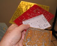
Pictures are very welcome...all you have and wanna show us...dogs, cats, bicicles, kids, motorcicles, audio appliances, family, house, tree, home, yourself and so on....of course the amplifier is the most important picture..but others are very nice too.... we are humans, not machines that assemble amplifiers.
regards,
Carlos
Your calm and clever method of research.
You did that by yourself...i gave you only psychological support and friendly company.
Thank you because you made the choice to a Dx amplifier.
I feel honored to have people alike you doing it...i see you know all tips and tricks... skilled in the good way....someone that knows the practice knowledge of how to do things... this is the best know how possible... i do think this is superior knowledge... Einsten once said that "curiosity is superior to knowledge"...i do think so.... knowledge does not allow you, alone, by itself, to do things real life...but curiosity creates the research style, to study things and obtain the practical knowledge to do things... this results in knowledge..but the opposite...the knowledge without curiosity transforms us in unflexible thinking machines that does not allow us to progress...not breaking myths, no progress is possible..without changing point of view...no progress too.
This amplifier sounds nice.... the sound does not loose too much when compared to the Dx Blame..they have something alike.... this one plays loud, has tight bass, nice treble and voices... a very good audio amplifier.
Check all VBE voltages...be sure all them have more than 490 milivolts..in special compare VBEs from drivers and output devices...the optimized value of VBE i always search for is 575 milivolts... accepting more to the VAS (600 to 640 mV)...i do not remember very well, but seem i have made some modification in the floating emitter resistance...the one is in between the driver's emitters..not sure if 150, 180 or 220 ohms....long time passed my dear.... i am sorry...i cannot remember exactly.
Pictures are very welcome...all you have and wanna show us...dogs, cats, bicicles, kids, motorcicles, audio appliances, family, house, tree, home, yourself and so on....of course the amplifier is the most important picture..but others are very nice too.... we are humans, not machines that assemble amplifiers.
regards,
Carlos
Last edited:
patience
is a virtue... i hope.
My amp has "played" but something is amiss. At first it is mostly distorted. Then, I turn up the input level and it comes to life. At this point it plays, though perhaps a bit veiled. Then a few crackles, pops and goes back to distortion again. It is similar in both channels. I can bring things 'back' but again, increasing the input level.
Measurements:
Vbe on both output devices is 0.6 volts and very stable.
Emitter to Emitter voltage on the output device pair starts out at a stable 35 mV, but then fluctuates wildly. Up to twice that level, without touching the bias servo potentiometer.
I haven't been able to safely reach the Vbe pins on the other stages as it's a bit of tight squeeze from the top side of the pcb. I will have to disassemble from the chassis to measure those.
These measurements are made with a) the input grounded b) the rail fuses in place (no protection resistors) and c) no load connected to the amp
Does any body have any hints?
Thanks
Ryan
Not a virtue, seems an error still remains
Increase the bias, you can do that till 300mA for test purposes without any problems....but despite the bias increase may help, seems to me you have errors as bias itself will not fix.... will just show you where to find....
Not a good idea to put boards inside the chassis while they are not tested first...now hard work to remove them, as you must test all transistors VBE that may help you to find where is the problem.
Continue to search, because this amplifier plays lovely and have no strange behaviors.
regards,
Carlos
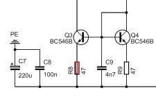
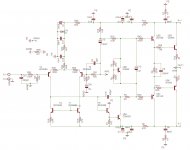
To new forum folks...here you have the schematic
Schematic attached.
Dx amplifiers you can see here:
http://users.tpg.com.au/users/gerskine/dxamp/
regards,
Carlos
Schematic attached.
Dx amplifiers you can see here:
http://users.tpg.com.au/users/gerskine/dxamp/
regards,
Carlos
Attachments
Here you have a sample of this amplifier sonics
Recorded using digital photo camera.
YouTube - HRII - Dx Amplifier - high bias 300mA
http://www.youtube.com/watch?v=pgxa3JnuKGk
regards,
Carlos
Recorded using digital photo camera.
YouTube - HRII - Dx Amplifier - high bias 300mA
http://www.youtube.com/watch?v=pgxa3JnuKGk
regards,
Carlos
Last edited:
This amplifier is sweet..to Rock and Roll it is perfect
It plays very loud and undistorted, sounds very good to this style of music.
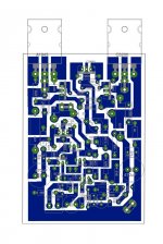
I will post some files about it, starting with Gerbers that allow you to modify boards to your own style and to order boards if you want...be free to use it and enjoy....not allowed to have profit, but to help comunitty offering nice designs to the people in group buy.
regards,
Carlos
It plays very loud and undistorted, sounds very good to this style of music.
I will post some files about it, starting with Gerbers that allow you to modify boards to your own style and to order boards if you want...be free to use it and enjoy....not allowed to have profit, but to help comunitty offering nice designs to the people in group buy.
regards,
Carlos
Attachments
Some files about the HRII.... you have this stuff in Greg home pages
Here:
http://users.tpg.com.au/users/gerskine/dxamp/
The schematic attached was the one used as reference (part numbers) to produce the layout
regards,
Carlos
Here:
http://users.tpg.com.au/users/gerskine/dxamp/
The schematic attached was the one used as reference (part numbers) to produce the layout
regards,
Carlos
Attachments
")
I strongly suggest you to go the MKIII-Hx group buy
This may be your last change to have a piece of history in your hands...and built by yourself... time is passing by.... the time you will be reading this will be past....in the future these circuits will be alike gold....not only the ones i have created..but all amplifiers produced in small quantity:
- " In the future these circuits will have the value of relics ... not only mine but all the plates produced in small numbers within this DIY forum, they will be rarities, antiquities and treasures .... amplifiers are manufactured by the thousands .... we do 50 or less kits for each model series .. little gems for their rarity, precious by the fact that you built, which creates extra value for your descendants .. one day an amplifier may be worth a lot of money for your children and grandchildren because it will be part of DIY forums, audiophile designs, will be part of the history of audio ... I'm old ... within 10 or 20 years I will be with the angels (or demons) .. then it will be worth even more, then think about it a bit."
regards,
Carlos
This amplifier is lovely...but we have others more modern with better performance
Build a Dx amplifier folks..i ensure you will never regret.
I found some boards Hugo Schultz, from Minas Gerais - Brasil, have sent me as a gift...i will assemble them....also some red boards from the MKII German group , a Dx switching power supply and a Stee design (Isy).
http://www.youtube.com/watch?v=N9xeOv08o3c
regards,
Carlos
Attachments
Last edited:
I built the DX HRII and it is oscillating at 20MHz (my comp cap is 100pF) does the type of BD139 matter 10 vs 16 different hfe's I'm using the 16 which has higher hfe could that be why its oscillating, also I used 100uF for bootstrap capacitor is that OK. I got it to oscillate less by removing the 10pF on the nfb resistor. To get all the oscillating to go away i put 39pf caps from the base's of the driver transistors to there rails. now the speaker is making all these weird clicks and pop noises and the music is all distorted. and with no signal the flat wave on the scope jumps around randomly and there is 200mv of DC offset.
Capacitors from base to colector...is this you call rails?
Maybe is what you want to say.... because in our situation is to connect from base to rails.... reduce them to 10pf...increase the compensation to 150 or 180 picofarads (Miller)... remove the one at the feedback line.
You know, the idea is to connect from base to colector, having colector resistance to rail or not.
The off set is adjustable.... try resistances (start with 10K) in parallel with the first transistor..... it has a current sink below..and the current sink have resistors..values goes from 47 to 100 ohms and i do not remember the HRII values... select the left hand one and install a 10K trimpot in parallel and try to reduce the off set.... first adjust the trimpot to read 10K....then install and go reducing the resistance and see if you off set reduces...... is it not reducing?... then install small trimpot (50 ohms) in series with that resistor and goes increasing the resistance.... when the off set is zeroed... then measure the trimpot resistance and substitute by a fixed resistor with the nearest values you have measured... you can install a second resistor in series or substitute for a single one that add both resistances (fixed plus the adjusted resistance adjusted in the trimpot and readed in your ohmeter)
If you have off set...or you have mismatched transistors (differential is the main ones) or you have errors in resistor values somewhere.
Interesting...first report about oscilations...and an interesting frequency.
Keep uncle charlie informed about your progress.
regards,
Carlos
Attachments
Last edited:
I do not know...usually do not oscilate even with high gain transistors
I have used 220 of gain without troubles...i do not know the reason why...check your circuit searching for mistakes first... check if your capacitor is really that value you imagine it is (capacitance meter).
I have no reports about troubles in this amplifier....so, i understand that a mistake while building is a possibility.... the board itself, component values or something missed.
Reduce gain of transistors and make modifications into the original design is something we do when we have reports saying the amplifier is oscilating...and several guys assembled and no report arrived saying this...so...i believe in a mistake.
In my mind what should be done is to search for errors and not to try to fix an unstable design, because no reports about unstabilities.
I know that people imagine the amplifier is a time bomb...this is easier to think..hard is to think we make mistakes...but for sure there is a mistake in your amplifier...and soon or latter you will find it.
regards,
Carlos
Last edited:
I soldered the new transistor in place (KSC3503D) and all signs of oscillation are gone, just a small amount of noise at 5mv. It sounds great!! There is 14mv of DC offset is that normal? Also when I was putting together the 2 channel I plugged the V- and V+ wires in backwards and the floating emitter resistor on the drivers caught fire. I replaced that resistor and the emitter degeneration resistors and it seems to be fine. I been listening to it for some time now, do I have anything to worry about, or should it be fine. I uploaded the PCB and circuit that I am using I just wanted to know if there was anything obviously wrong with them. Thanks.
Attachments
- Status
- This old topic is closed. If you want to reopen this topic, contact a moderator using the "Report Post" button.
- Home
- Amplifiers
- Solid State
- Dx HRII, High Resolution II - now a thread for this veteran