Hi,
Another way to do the agc is to use the outputs from the statevariable oscilator as sin and cos and use the old trig identity cos^2 + sin^2 = 1. Then, in theory, you
don't have to filter the signal.
There is a a Philips res rep from 1974 ( in german ) by Meyer-Ebrecht describing this.
/örjan
Neat idea!
You still need to filter the signal, but not nearly as much, and that is important.
Best,
Bob
Hi,
Another way to do the agc is to use the outputs from the statevariable oscilator as sin and cos and use the old trig identity cos^2 + sin^2 = 1. Then, in theory, you
don't have to filter the signal.
There is a a Philips res rep from 1974 ( in german ) by Meyer-Ebrecht describing this.
/örjan
For this to work properly, cos an sin amplitudes should be closely matched. If they are not, you get ripples just as with a full-wave rectifier.
BTW, there was a later article on the same subject:
Fast Amplitude Control in Twin-T Bridge RC Oscillators
By Filanovsky, I.M.; Fortier, G.J.
Electronics Letters
Page(s): 791 - 792, August 29 1985
Volume: 21 Issue:18
This is a good point, and thanks for the reference. Just thinking out loud, if the fundamental is at 1 kHz, the ripple frequency from the FWR will be at 2 kHz. I'm gussing that the ripple frequency due to mismatch of sin and cos amplitudes would be at 4 kHz. Does that sound right? That could be a further advantage of the sin-cos squared approach.
Cheers,
Bob
Quadrature anyone -- the "Boonton 1120 Frequency Source"
An externally hosted image should be here but it was not working when we last tested it.
This is a good point, and thanks for the reference. Just thinking out loud, if the fundamental is at 1 kHz, the ripple frequency from the FWR will be at 2 kHz. I'm gussing that the ripple frequency due to mismatch of sin and cos amplitudes would be at 4 kHz. Does that sound right? That could be a further advantage of the sin-cos squared approach.
Cheers,
Bob
I did a little simulation - it appears that the ripple would still be at 2kHz, and that an imbalance of quadrature signals before squaring both adds ripple and affects the average level of (sin^2+cos^2). There still may be an advantage compared to a FWR in that the (unfiltered) ripple can be much smaller, allowing for shorter time constant of the filter and thus faster settling.
I'll try to implement this once I complete your THD analyzer - I am just done with bench testing
")
Quadrature anyone -- the "Boonton 1120 Frequency Source"
An externally hosted image should be here but it was not working when we last tested it.
Hi Jack,
Thanks for posting this. It will take awhile to absorb...
.Cheers,
Bob
I did a little simulation - it appears that the ripple would still be at 2kHz, and that an imbalance of quadrature signals before squaring both adds ripple and affects the average level of (sin^2+cos^2). There still may be an advantage compared to a FWR in that the (unfiltered) ripple can be much smaller, allowing for shorter time constant of the filter and thus faster settling.
I'll try to implement this once I complete your THD analyzer - I am just done with bench testing
That's intersting about the performance of the sine2+cos2 circuit. That result was not intuitive to me.
Keep us posted on your progress with the analyzer and best of luck!
Cheers,
Bob
I have ancient Heathkit stuff including distortion analyzer, audio generator. and audio voltmeter. (I also have a Balantine if anybody wants to make me an offer.)
But now-a-days, I just use a free computer oscilloscope program. Pity there's nothing current and free on the Mac now but my old MacCRO freeware still works pretty good. The bestest most wonderful function is the spectrum analyzer. You can see noise, harmonics, hum, and general junk many dBs below the fundamental tone and further enlarge the scale showing the noise floor, assuming you've double-checked that the measurement system and audio oscillator are clean.
The spectrum analyzer doesn't produce actual numbers, but it sure fills your eye with meaningful information. I suppose you could eyeball some test device of known distortion, say ".005" and then compare it to the device you are examining or building.
it's wonderful to have played in hi-fi for more than 50 years: you couldn't believe how amazing it seems to buy, build, or be able to test stuff today compared to then.
I have ancient Heathkit stuff including distortion analyzer, audio generator. and audio voltmeter. (I also have a Balantine if anybody wants to make me an offer.)
But now-a-days, I just use a free computer oscilloscope program. Pity there's nothing current and free on the Mac now but my old MacCRO freeware still works pretty good. The bestest most wonderful function is the spectrum analyzer. You can see noise, harmonics, hum, and general junk many dBs below the fundamental tone and further enlarge the scale showing the noise floor, assuming you've double-checked that the measurement system and audio oscillator are clean.
The spectrum analyzer doesn't produce actual numbers, but it sure fills your eye with meaningful information. I suppose you could eyeball some test device of known distortion, say ".005" and then compare it to the device you are examining or building.
it's wonderful to have played in hi-fi for more than 50 years: you couldn't believe how amazing it seems to buy, build, or be able to test stuff today compared to then.
I grew up with the same limitations. Because I could not afford really good test equipment (the Tek and HP stuff I lusted after at work at Bell Labs), I ended up building a lot of my own (in addition to Eico and Heathkits). I spent many hours studying the schematics in the Tek and HP service manuals for the equipment at work.
Nowadays, it is truly wonderful how much can be done with a PC and a good sound card. This is especially so for spectral analysis. Spectrum analyzers have always been expensive. Many years back I treated nyself to a used HP 3580A spectrum analyzer, but my wallet really took a hit.
I use a Juli@ soundcard with a variety of mostly free software out there and enjoy it a lot.
Cheers,
Bob
Pinch-off FET voltage
Hello everyone,
I measured the pinch-off voltage, of some FET in my possession, as mentioned by Bob.
Here are the voltages:
2SK30A-Y 1,60V
2SK30A-GR 2,20V
2SK246 BL 3,16V
2SK246 GR 2,10V
2SK170 BL 0,60V
BF244 C 4,50V
Question: Which of these is more suitable for this application? Or anyone?
Thanks
giuliano
The 2N4091 used in the original THD analyzer design had the following rated characteristics:
rds_on: 30 ohms
Idss: 30 mA
Vgs_off: 5-10V
The low on resistance and high threshold voltage allow this device to provide adequate AGC control range with low distortion (especially the high Vt).
Of the above devices, either the 2SK246 BL or the BF244C would probably be the best choices, especially if their Rds_on is below 50 ohms.
Cheers,
Bob
So I choose the device that must have high Vgs-off and low on resistance, ok!
One more thing, Bob, the use of AD630 instead of MC1496, would improve the performance of the instrument?
Thanks Bob
Next time
giuliano
I've never used the AD630, but it looks like a nice part. Some re-design would be necessary to incorporate it, and that does add some risk. I'm not sure the swap would improve performance because I don't thing the 1496 devices are limiting the performance of the analyzer.
Cheers,
Bob
Hi abraxalito,
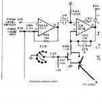
I refer to Q7 FET (see image).
I think it's so :
biasing to -15V, it has several Mohm between D and S, then R88 is isolated from GND.
Placing the gate to ground, it switches to max conduction and "connects" R88 to ground (+ Rds on).
I think it's so.
Ciao
Giuliano
I refer to Q7 FET (see image).
I think it's so :
biasing to -15V, it has several Mohm between D and S, then R88 is isolated from GND.
Placing the gate to ground, it switches to max conduction and "connects" R88 to ground (+ Rds on).
I think it's so.
Ciao
Giuliano
Attachments
Afters a couple of years with no post I thought that finally I might have something to add in this thread.
I've implemented this, and it works--but not as well as you might think. As noted above you'll need to trim the sum of the two squares for every frequency range to incorporate inherent time-constant mismatches of the integrator stages. Even then there's quite a bit of residual left due to feedthrough and nonlinear errors from the multipliers. By operating them at lower level at least the later may be reduced, by then you'll get more noise. Choose your poison.
The track-and-hold/sample-and-hold approach as shown in the Boonton schematic above is much better. Near-zero correlated residual. Noise is an issue, but it is easily handled by amplifying the error signal before the sampling stages. There are several commercial oscillators which are based on this, including the AP System One and at least two HP oscillators.
A scheme I want to try once is thermal implementation of the trigonometric approach; this has been used in AC reference standards and works by sensing the sum of the heat dissipated in two resistor feed from the two integrator output stages. While time constant mismatch is still an issue at least linearity and amplitude flatness should be rather decent.
Samuel
I agree--adding the squares of the two quadrature signals is the most elegant solution. The squarer can be the AD633 (true 4-quadrant multiplier), a relative bargain around $4 each in volume.
I've implemented this, and it works--but not as well as you might think. As noted above you'll need to trim the sum of the two squares for every frequency range to incorporate inherent time-constant mismatches of the integrator stages. Even then there's quite a bit of residual left due to feedthrough and nonlinear errors from the multipliers. By operating them at lower level at least the later may be reduced, by then you'll get more noise. Choose your poison.
The track-and-hold/sample-and-hold approach as shown in the Boonton schematic above is much better. Near-zero correlated residual. Noise is an issue, but it is easily handled by amplifying the error signal before the sampling stages. There are several commercial oscillators which are based on this, including the AP System One and at least two HP oscillators.
A scheme I want to try once is thermal implementation of the trigonometric approach; this has been used in AC reference standards and works by sensing the sum of the heat dissipated in two resistor feed from the two integrator output stages. While time constant mismatch is still an issue at least linearity and amplitude flatness should be rather decent.
Samuel
Hi abraxalito,
I refer to Q7 FET (see image).
I think it's so :
biasing to -15V, it has several Mohm between D and S, then R88 is isolated from GND.
Placing the gate to ground, it switches to max conduction and "connects" R88 to ground (+ Rds on).
I think it's so.
Ciao
Giuliano
That FET is indeed used as a switch. When on it increases the gain of that stage by a factor of 10. It is in the distortion residual path, so that any small amount of distortion it adds will not impact the analyzer's performance. A relay in that position will work fine, but it will likely not improve analyzer performance.
Cheers,
Bob
One of the Cordell's for sale on EBay:
Cordell Distortion Analyzer / Audio Generator - eBay (item 290395303501 end time Jan-31-10 17:29:27 PST)
Cordell Distortion Analyzer / Audio Generator - eBay (item 290395303501 end time Jan-31-10 17:29:27 PST)
- Status
- This old topic is closed. If you want to reopen this topic, contact a moderator using the "Report Post" button.
- Home
- Amplifiers
- Solid State
- My implementation of the Cordell Distortion Analyser