Of course I meant the DM.
Probably it was me who started the confusion. Typed MA instead of MD...
Samuel
Distortion Magnifier
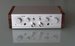
Finally finished (95%; need to get my 24 bit sound card & software going for some more measurements).
")
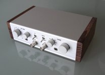
The BNC sockets give a sense of scale. Overall size is 160x100x55mm (tiny).
Input from DUT and Signal Source are both balanced, using 3.5mm phono jack as connectors.
Patrick
.
Finally finished (95%; need to get my 24 bit sound card & software going for some more measurements).
The BNC sockets give a sense of scale. Overall size is 160x100x55mm (tiny).
Input from DUT and Signal Source are both balanced, using 3.5mm phono jack as connectors.
Patrick
.
Attachments
Last edited:
Someone PMed me and asked :
"How do we connect and use your Distortion Magnifier V2 Public with a sound card ?"
The DM subtracts the original signal from the output of the Device under Test (DUT), while adjustments for gain and phase. The remaining output is then distortion (and noise). You may want to analyse the frequency spectrum of the distortion, or determined the RMS value, .. etc. Here, you can use a sound card with freeware.
Of course you can also use professional equipment for the same purpose.
Patrick
I (almost) completed my THD analyzer, but I get too high measurement floor at -90dB/0.003% across all frequency ranges. I did not implement the tracking filters and used the fixed ones, but this is not likely to explain a floor 20 dB higher than it should be. With filters on, the scope shows it's mostly third harmonic.
I'd be grateful for an advice on where to look at.
I'd be grateful for an advice on where to look at.
Measure at all three outputs of the state-variable ring of the oscillator. This will indicate if the excess distortion is in the analyzer (if all readings give identical, too high results), the output section of the oscillator (if all readings give identical, expected low results) or the oscillator itself (if all three readings are different).
Samuel
Samuel
I (almost) completed my THD analyzer, but I get too high measurement floor at -90dB/0.003% across all frequency ranges. I did not implement the tracking filters and used the fixed ones, but this is not likely to explain a floor 20 dB higher than it should be. With filters on, the scope shows it's mostly third harmonic.
I'd be grateful for an advice on where to look at.
If I had to guess, I'd think it might have something to do with the agc in the oscillator. If it is third harmonic, bear in mind that if you double the signal level, the distortion percentage will go up by a factor of four. Sometimes you can take advantage of this relationship to find out what is setting the floor.
If you attenuate the level going from the oscillator to the analyzer input, what happens to the distortion reading? If you adjust the oscillator agc to double or halve the operating level of the oscillator, what happens to the distortion reading?
Make sure you are using the right kind of JFET in the oscillator agc.
Make sure the oscillator full-wave agc detector is giving true, balanced full-wave rectification.
Make shure there is very little signal ripple in the control signal driving the JFET.
Cheers,
Bob
- Status
- This old topic is closed. If you want to reopen this topic, contact a moderator using the "Report Post" button.
- Home
- Amplifiers
- Solid State
- My implementation of the Cordell Distortion Analyser