Don't understand??? You are offering these specific parts or what?
From Australia, shipping and taxes will kill you. But you could have
drop shipped from locals Digikey, Arrow, Allied, Newark, or Mouser.
I got a bucket of real parts (not exactly the ones requested) only
2 hours away. Just need to ask one of his adult friends to grab it
next time they drive through Dallas in course of normal business.
No special trip or heavy shipping.
I'm not sending anything potentially dangerous (power supplies and
huge caps) directly to any minor. Don't even want to know contact
info. If he wants to give work address of parents or teacher, thats
an entirely different situation... Any plausible veil of "supervision".
I'm not worried what Keantoken will do, its parents and lawyers I
don't trust. In US culture, one has to be paranoid that way.
-------------------------------------------------------------
I forgot to mention a pair of Bournes 10K (Audio Taper) pots.
Lots potentially useful small parts I may have forgot to mention.
Thinking toward Allison style circuitry, not entirely random junk.
OK, so maybe 6DJ8 triodes aren't directly relevant, shoot me.
Last edited:
keantoken,
Regarding post 159, gm for germanium is the same as it is for silicon. As a little background:
Ic=Is*(e**Vbe/(Nf*Vt)-1) ;a good approximation
gm=dIc/dVbe=q*Ic/Nf*K*T ;negelecting the -1 term in the above expression
Vt=K*T/q
where Ic=collector current
Is=saturation current (not to be confused with the collector current of a saturated transistor)
q=electron charge (1.602e-19)
K=Boltzmann's constant (1.38e-23)
T=Kelvin temperature ;TKelvin=Tcentegrade+273
Nf=constant ; normally about 1 for both silicon and germanium
The big difference between germanium and silicon is Is. Is for Ge it is 1000 to 10000 times more than Si. I don't see any advantage in using Ge, because it's high frequency performance is very poor.
Last edited:
The germaniums are 2N169A and 2N1373. Forget about finding spice models.
One's a funny hat shape, the other a TO5 can.
Supertex VN0106 and VP2206: Blew it, specs on these two aren't very close.
I dunno, maybe they are close enough, but not quite what I was thinking.
They are both the TO92 package style...
You got enough junk here to make noises with (in stereo) , for sure.
Last edited:
I've completely also misunderstood Aksa's post. Somehow I didn't grasp that
he had sent actual PCBs that needed those specific parts. I doubt any of the
junk I've been collecting for KT in "the infamous bucket" is gonna substitute.
Whatever, its still good stuff for experiments.
he had sent actual PCBs that needed those specific parts. I doubt any of the
junk I've been collecting for KT in "the infamous bucket" is gonna substitute.
Whatever, its still good stuff for experiments.
I don't really have much to say but... Thanks!
Ken, you are not obligated to try to get me things on the list Hugh gave. What you have in the bucket so far is quite good enough. Another person has offered to send me some parts. Thanks. I know of another family member's address I can send to where no minors live. I'll PM you when I've checked with them.
Sawrey, thanks for the info. I might still try using them, just to see what happens.
- keantoken
In the YAP thread, you posted a three transistor CCS. But my reply to you
relates also to this Allison circuit in general... About carrier saturation, and
recovery time. I don't think our Sim is able to show you storage lag effects
when you run VCE so crazy low... Less or equal than the VBE diode drop.
http://home.mira.net/~gnb/audio/bakerclamp.html
About halfway down, he shows some graphs that may be eye openers.
LTSpice PDF offer
I for one would be interested.
Cheers,
Dave
Also I believe some (many?) people do not know how to use LTSpice, the simulator I am using, correctly. When used correctly, the simulator can be a powerful friend, but only if used correctly. If someone is interested, I can compile a PDF detailing the proper use of LTSpice.
I for one would be interested.
Cheers,
Dave
I for one would be interested.
Cheers,
Dave
I will see what I can do.
However, I will point some things out:
1: I am an "average" user who has learned enough to keep from being fooled if I somehow misuse the simulator. I don't have deep technical knowledge that isn't necessary for hobby-level use.
2: I still haven't figured out how to install subcircuits and complex models into LTSpice! If you need help with this, the Yahoo group is the place to go. It's nothing too complex, I just haven't bothered with it because I prefer discrete circuitry.
In all, I might not be the person best suited for drafting such a resource (although I felt confident at the time of that post), though I can throw together a quick PDF informing a new user of good practices and some hidden catchups they may encounter. So I would appreciate any feedback once I post my first draft. It might take some time to get to it, but I will post a thread when I do.
Ken, I assume the storage time has to do with Cob becoming larger as Vce decreases? I agree that the Vce is very low, but I don't think they're in saturation. Maybe you should explain?
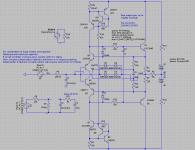
Here is my latest diagram, with input protection. It's taking form, though I haven't gotten to prototype it yet.
- keantoken
Attachments
Member
Joined 2009
Paid Member
Folks,
Along with many others, I am deeply impressed by Keantoken's contributions here, and I would like him to get something back in return. [...] Be assured that this is a very good cause, KT is just 16 years old, and shows more potential than I've ever seen in a young man of his age. Us wrinklies need to help the fresh-faced designers of tomorrow!
Hugh,
I wouldn't put you in the wrinklies class (yet
 )but this is just the kind of thing that puts you in the 'elder statesmen' category. I don't mean to embarrass Keantoken by highlighting your praise, but it's so nice to see this kind of thing on the Forum.
I know for sure I was never this knowledgeable about electronics when I was 16 (nothings changed since !)
Collectors of Q3 and Q4 have 2 diode drops worth of standing voltage, good.
I'm not sure I can say the same for Collectors Q5 Q6? Which need only fwd
bias single emitters of Q1 Q2 and a small series resistance.
What if you add a Schottky or Darlington drop in series with the bases of Q1
Q2? Thus preventing Q5 and Q6 collectors from working at such extreme low
voltage.
I'm not sure a sim here would show the benefit, but a real circuit might.
I'm concerned that these must be flooded with carriers to achieve such low
VCE drop, and the quiescent current is fairly low to get rid of it quickly.
I would have used Darlington or CFP output configuration, but I soon found that this did not work well at higher frequencies. It is necessary to use single EF to achieve this high bandwidth with a circuit this complex as far as I know. I suspect putting a diode in series with the bases will have a similar effect, but I will try it.
Okay, diodes in series with the bases does not work very well at all at HF and isn't good for stability either. But emitter diodes are workable and don't seem to degrade response.
- keantoken
Okay, diodes in series with the bases does not work very well at all at HF and isn't good for stability either. But emitter diodes are workable and don't seem to degrade response.
- keantoken
Folks,
Here's a few parts that KT needs:
4 x 0R33 3W 4507 Vishay-Dale smd resistors
4 x 2SC5200 (two matched pairs if possible)
4 x 2SA1943 (ditto)
2 x 2SC4793
2 x 2SA1837
2 x 2SC3423
Four each of the following half watt, MF resistors: 33K, 1K5, 2R2, 12K, 330R, 100R, 2K2, 3K3 (1W), 100K, 10R, 150R, 33R, 22R, 6K8, 10R (1W).
Four each of the following caps: 100uF 63VW, 47uF 50VW, 820p silver mica, 22pF sm, 15pF sm, 100nF 160V MKP, 100nF 100V ps, 2K 3296 bourns trimpot, 200R 3296 bourns trimpot.
Hugh
Folks,
If you would like to help, please PM Keantoken (Anthony) to get his mailing address. Be assured that this is a very good cause, KT is just 16 years old, and shows more potential than I've ever seen in a young man of his age. Us wrinklies need to help the fresh-faced designers of tomorrow!
Hugh
16, I'm very impressed.
I have
4 x 2SC5200
4 x 2SA1943
which I can send (all the way from New Zealand). I bought these several years ago from digi-key so they are at least guaranteed originals but not matched pairs.
KT, drop me an e-mail if you like, perhaps someone else can supply matched pairs though.
Dave, I tried my hand at that guide yesterday. I decided just to make a forum post rather than trying to make a PDF look good. I got about halfway through, and by an honest mistake my browser refreshed and I discovered my post had been erased. Discouraging, but I'll consider that to have been my rough draft.
I don't think anyone should be too surprised about my knowledge... I've only been fiddling with the simulator constantly for 3 years.
- keantoken
I don't think anyone should be too surprised about my knowledge... I've only been fiddling with the simulator constantly for 3 years.
- keantoken
Member
Joined 2009
Paid Member
KP,
You could run it at 24V rails with no problem at all, though compensation would need changing. Equally, four stacked 24V smps would work without problem too as long as there were two pairs of outputs per module.
Thank you, and others, for your contributions.... KT will be 1 happy camper!
Cheers,
Hugh
Regarding transistor storage time. It is caused by stored charge in the base emitter junction and in the simulator it is related to Tr. If you look at the base current during the storage time of a transistor you will see a reverse current. The Baker clamp prevents saturation of the CE junction and thus prevents excess charge from accumulating.
- Status
- This old topic is closed. If you want to reopen this topic, contact a moderator using the "Report Post" button.
- Home
- Amplifiers
- Solid State
- Simulation Analysis of several unique Allison-based output stages.