Hi,
www.Tubecad.com used to publish various distortion and noise cancelling circuits, with extensive design notes for the tube fan.
I do not know if any of the topologies could carry over to SS.
Our experts will have a view on this.
regards Andrew T.
www.Tubecad.com used to publish various distortion and noise cancelling circuits, with extensive design notes for the tube fan.
I do not know if any of the topologies could carry over to SS.
Our experts will have a view on this.
regards Andrew T.
avoid symmetry
Symmetric stages just turn even harmonics into odd harmonics, so avoid them. Use class A single ended stages and keep amplitudes low enough to avoid entering saturation regions. Any transfer function with an S shape will produce odd harmonics. Using emitter or source degeneration will help linearize too.
Current mirrors with gain are about the only practical way to cancel harmonic generation. (well, other than the usual neg. feedback or feedforward strategies) Vacuum tubes, interestingly, work even better than solid state for current mirrors with gain. Since they are pretty religious about conforming consistently to a fixed power law transfer function to get wide range matching between devices. The current mirror circuit in tubes remains pretty obscure in practice yet. There is the voltage mirror circuit too, but is only barely useable in tube circuitry, totally useless in SS circuitry.
If one gets REALLY desperate, you might consider distributed gain parametric amplifiers, aka "wires with gain".
Finally, one could just use a truly linear device to avoid odd harmonics. The only one I know of, with fundamentally linear mode of operation, was the beam deflection tube, although it does saturate at high levels and subsequently produces odd harmonics at those levels. Almost no tubies use them since they are hard to work with, sensitive to magnetic fields, and must be selected to avoid a substantial percent of defective ones still available.
In theory, square law devices, like FETs, would only generate even harmonics which could then be canceled in P-P. But in practice, their transfer curves vary from exponential at low currents, to square law, to finally near linear law at high currents, then sublinear as saturation effects set in.
Don
Whao, that's an explanation! Thank you.
Could you just give me more details about a few things?
-I know the current mirors, but what is a curent miror with gain?
-Why do symmetric stages turn even harmonics into odd ones?
-How can you predict the harmonics by looking at the transfer function?
-Why does PP cancel even harmonics?
Could you just give me more details about a few things?
-I know the current mirors, but what is a curent miror with gain?
-Why do symmetric stages turn even harmonics into odd ones?
-How can you predict the harmonics by looking at the transfer function?
-Why does PP cancel even harmonics?
Some of this input is faulty. First, push-pull class A design cancels even order harmonics, BUT local feedback, even created by another active device in series, will generate odd harmonics from the even harmonics; for example, in a differential pair.
However class B design, such as an output stage, DOES turn even order harmonics into odd order harmonics, because each output device only amplifies 1/2 the sine wave making up the total signal.
Personally, I usually chose to use push-pull class A and differential input stages for solid state. This reduces distortion in general, and makes for DC stable designs. The small amount of extra third generated is not very much, or very important.
However, tubes are another story. Usually, triode tubes can be made so linear that it is a toss-up whether they should be used differentially, except for special applications.
Third harmonic cancellation is another story. It is difficult to do. Still, pure third is not so bad. After all, analog magnetic tape had typically 1% third harmonic at operating level, increasing to over 15% on peaks, yet it could sound pretty darn good. Third harmonic distortion, and its IM products are still close to the music.
It is the 5th, 7th and 9th harmonics that should be removed or avoided at any cost.
Hi Alex,
I'll try to answer what I can.
a) the current mirror with gain just uses a larger (or parallel) device(s) for the output versus the input device. As long as the transfer curves are the same, one gets a larger "mirrored" current in the output device than in the input device for the same base, emitter or grid voltage common to them.
b,c,d) probably have to look at a DSP or Signals book like Lathi's or Oppenheim's to get a good mathematical explanation here. I will try to give an example.
Generally, the power function of the non-linearity gives an indication of the order of the harmonics generated. For a second order function, square law, the output has the input Sin(theta) squared, which is equivalent to Sin(2*theta + phasefactor), so second harmonic generated. Similarly, a cubic function produces 3rd harmonic but also can produce lower order odd intermods between two different input sine waves.
Have a look at the "multiple-angle relations" trigonometry table in a math reference book like the CRC Standard Math Tables book for a list of these formulas.
You will notice if plotted, that a square law function gives a parabola which has signal compression at one end, where-as a cubic function has compression in the center. Hence the symmetry effect (also consider, even powers of a - signal give + versus odd powers of a - signal give -).
By using a diff. amp. stage or P-P stage, the single ended compression effects of the individual devices get arranged so as to produce compression symmetrically at the center of the range for class AB or at the ends of the range for class A. So is either like a cubic (or higher odd power) law or like having a 1 over cubic power law. (By dividing out, one will get a bunch of fractional order odd power terms. ) So, the idea of "cancelling even harmonics" in these cases is really a little misleading, the non-linearity is still there, just with a different symmetry. But some of the curvature effects that would give even harmonics do cancel, so some truth to it. ( a good example of this is when using square law devices)
Anyway, there are some generally known rules about symmetry of waveforms and their harmonic content that can be found in the DSP or Signal theory books. The more sharply compressed (or expanded) the transfer curve is, usually the higher the order of harmonics. The symmetry between + and - signal compression (or expansion) giving odd harmonics.
Hope that helps. Best to check the books.
Don
I agree with John C. on the practicality and reasonableness of using a differential input stage as long as the input signal difference is kept within 50 mV or less, which would be the case for a NFB design. The smaller the input difference range (usually by means of larger NFB) the lower the residual odd order distortion from the diff. stage. For a no, or low, feedback design this could be a problem however.
Yes, the class A versus class B P-P output does make a big difference concerning even order cancelation versus conversion to odd order. More of the transistor nonlinearities get cancelled in class A P-P since it is the sum of their transconductances that matters and both are operating simultaneously there. So a lot MORE odd order distortion is left in class B versus class A.
However, from a symmetry viewpoint, both are producing odd order distortions. Depends on how religiously one wants to avoid odd order distortion to make one resort to a single ended output. The single ended output "could" (theoretically if saturation effects are avoided) avoid the odd harmonics but would have a higher overall (from even order) distortion level than the class A P-P stage. To really suppress the residual odd order distortion in the class A P-P stage, one might consider a Hawksford style error correcting output add-on as more practical.
Don
there is no way of simple canceling odd harmonics
only things you can do are:
1. have low distortion in general
2. produce extra even harmonics if you believe they "mask" odd ones
single ended tube of fet without feedback do produce much odd harmonics but they are better because even exist too.
There is no odd-harmonics overkill, 'biggest' one is the second.
By transfering this to symetrical you cancel even while keeping odd.
Another thing is that class A produces low order harmonics and class B high order too (I mean aproximate loss in harmonic amplitude per decade is lower)
regards
Hi darkfenriz,
Practically speaking I agree with you, but theoretically there IS a way to cancel odd (and even) distortion harmonics using current mirrors. The two active devices need only have IDENTICAL non-linearities for the mirror to cancel distortions.
Lets take two 3/2 power (thermionic diode and tube - pentode) devices as an example. Each device gives output current proportional to the 3/2 power of input voltage. In the mirror circuit, the first device (diode) is driven with a current and produces a voltage of the 2/3 power of the current. The second device (pentode) takes this voltage as input and gives output current of 3/2 power of the input. Net result is linear current in to current out despite the nasty 3/2 power operation law. Same thing happens in the solid state case but with exponential law operation. The current mirror is effectively doing perfect pre-anti-distortion followed by distortion.
A simpler way to visualize this is for a given grid voltage (or base / emitter voltage in SS case) the two devices must produce the same currents. To get gain, one uses more (or larger) device for the output. The catch is how to get truly IDENTICAL device characteristics. For tubes, the 3/2 law is pretty stable due to physics, for SS you need an IC or matched transistor array.
2) The ideal triode in single ended operation also can produce linear gain (no odd harmonics) if it is loaded with a current source like load. Practically speaking, resistors get used for loads, and triodes have manufacturing and design imperfections, so not so linear after all. For solid state, one is out of luck, no triode like devices, yet.
Don")
Practically speaking I agree with you, but theoretically there IS a way to cancel odd (and even) distortion harmonics using current mirrors. The two active devices need only have IDENTICAL non-linearities for the mirror to cancel distortions.
Lets take two 3/2 power (thermionic diode and tube - pentode) devices as an example. Each device gives output current proportional to the 3/2 power of input voltage. In the mirror circuit, the first device (diode) is driven with a current and produces a voltage of the 2/3 power of the current. The second device (pentode) takes this voltage as input and gives output current of 3/2 power of the input. Net result is linear current in to current out despite the nasty 3/2 power operation law. Same thing happens in the solid state case but with exponential law operation. The current mirror is effectively doing perfect pre-anti-distortion followed by distortion.
A simpler way to visualize this is for a given grid voltage (or base / emitter voltage in SS case) the two devices must produce the same currents. To get gain, one uses more (or larger) device for the output. The catch is how to get truly IDENTICAL device characteristics. For tubes, the 3/2 law is pretty stable due to physics, for SS you need an IC or matched transistor array.
2) The ideal triode in single ended operation also can produce linear gain (no odd harmonics) if it is loaded with a current source like load. Practically speaking, resistors get used for loads, and triodes have manufacturing and design imperfections, so not so linear after all. For solid state, one is out of luck, no triode like devices, yet.
Don
Hi, Smoking amp,
I dont understand that current mirror explenation. Are you saying to use current mirror in the place of LTP (input differential) or somewhere else in audio amp topology?
Is this mean the so called "current feedback" that is formed by current mirrors everywhere, do not make odd harmonics?
I dont understand that current mirror explenation. Are you saying to use current mirror in the place of LTP (input differential) or somewhere else in audio amp topology?
Is this mean the so called "current feedback" that is formed by current mirrors everywhere, do not make odd harmonics?
Hi Lumanauw,
I would use the current mirrors with gain for intermediate gain stage(s), say the VAS replacement. Would still use a diff. LTP for input since we need to go from voltage input to current for the mirror stage(s). ( or see inverting version below) I recall Janneman pointed out an IC op amp made with current mirrors with gain a short while back. Would need to seriously degenerate the LTP emitters to handle input signal swing if no global NFB were contemplated. I suppose one could use a complementary mirror output stage like Mr. Evil's schematic but it would be a high impedance output so one would be forced to use global NFB to fix that.
Ideally the current mirror doesn't produce any distortion (current gain wise), reality is something else. How close can you match the transistors transconductance curves is the real question. I think there are some 4 transister matched array chips around, but they only would give a current gain of 3 using 3 in parallel for the output of the mirrors.
Mr. Evil,
You are on the right track, but a few fixes are called for I think. The node between Q3, Q4, R3, R10 is a rather low impedance point. So two possibilities come to mind. By adding another complementary current mirror with gain stage in the lineup we can make the output inverting with respect to the input. So can use the whole thing as a standard inverting amplifier with global NFB.
The other possibility would be to put a symmetric/complementary dual LTP input stage in for voltage to current conversion of the input signal and feedback input. [Another, simpler variation, might be something like the tied complementary emitter input stage for a (voltage derived) current feedback amp., with the tied bases or gates used for the signal input. This provides current outputs to each rail direction conveniently for the mirror stages.]
Of course the current mirrors need to be of the current gain variety. With a complementary mirror output stage as you have shown, one will need a fair amount of loop gain to provide forward gain as well as to control output impedance. (unless one wants to make one of those trendy transconductance amplifers.) Maybe a more practical output would be to just use a class A P-P emitter follower stage tacked onto the present mirror output point. No doubt some other ways can be conjured up too.
Don
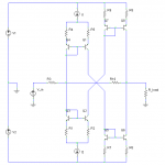
Ok, here's a variation on the idea: With the addition of a common-emitter input stage (before anyone says it - no it's not another current mirror per se if you look at it closely!), it's now inverting and high-impedance input.
Some quick simulation suggest fairly low distortion, consisting mostly of 2nd and slightly less 3rd harmonics, with higher orders much lower. Not bad for something that's still reasonably simple. It's not hard to alter it so it has no global NFB, if you like that sort of thing.
Some quick simulation suggest fairly low distortion, consisting mostly of 2nd and slightly less 3rd harmonics, with higher orders much lower. Not bad for something that's still reasonably simple. It's not hard to alter it so it has no global NFB, if you like that sort of thing.
Attachments
Nice circuit!
Q1 and Q3 provide offset bias voltages for Q2 and Q4. Lots of possibilities here to do variations on the theme:
(Output voltage derived) Current Feedback Amp. version:
R16 feedback could be connected to the R3,R12 point (instead of grounding), maybe need another complementary mirror stage in the chain to get inversion right then.
Low output impedance variation:
Use a P-P class A emitter follower output stage after the last complementary current mirrors.
R10 and R11 could be changed to current sources to eliminate power supply sensitivity I think.
Now all we need is for Janneman to drop in and tell us which famous IC op amps we've re-invented now.
Don
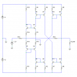
Q9 and Q12 collectors are the only points with significant signal swing on them and probably are accounting for the bulk of the remaining distortion. By cascoding these output transistors I'll bet the distortion cleans up even more. Also could use one of the fancy cascoded type current mirror configurations for the final mirrors too (instead).
Don
Don
This is usually the way of thingssmoking-amp said:...Now all we need is for Janneman to drop in and tell us which famous IC op amps we've re-invented now...
But no matter; it's better than always building standard diff+vas+follower amps!I've attached a schematic of that. It does decrease distortion a bit, and increases open-loop gain, but it also adds a peak in the frequency response. I'll have to work out where to put some frequency compensation for that. I also changed the preceeding current mirror to... errr... I'm not sure of the proper name for those.smoking-amp said:Q9 and Q12 collectors are the only points with significant signal swing on them and probably are accounting for the bulk of the remaining distortion. By cascoding these output transistors I'll bet the distortion cleans up even more. Also could use one of the fancy cascoded type current mirror configurations for the final mirrors too (instead).
Don
True that it would not be possible to get current gain with a normal current mirror, but in may cases only voltage gain is required. In the above circuit the input stage has high current gain, so as long as it's not used in a high-power application it should be fine. It might also be possible to use a current mirror with gain to avoid adding too much distortion from a normal output stage.darkfenriz said:hi smoking-amp
your way of thinking is very nice and creative, but it would be very hard to choose 'small current' and 'huge current' device, which have identical distortion. If you use similar devices you won't amplify anything (nomen omen: a mirror)
Attachments
smoking-amp said:Nice circuit!
[snip]Now all we need is for Janneman to drop in and tell us which famous IC op amps we've re-invented now.
Don
Errr... OPA622, half of it, oh no, these are obsolete, ehh, AD844, sans the buffer part...
But I DO believe that it is important to be creative and THINK about it and develop these things. It really isn't that much of a deal that someone else had the same thoughts. Who said it in these pages, "if you look down you'll see the giant on whose shoulders you stand".
Jan Didden
Mr Evil said:Ok, here's a variation on the idea: With the addition of a common-emitter input stage (before anyone says it - no it's not another current mirror per se if you look at it closely!), it's now inverting and high-impedance input.
Some quick simulation suggest fairly low distortion, consisting mostly of 2nd and slightly less 3rd harmonics, with higher orders much lower. Not bad for something that's still reasonably simple. It's not hard to alter it so it has no global NFB, if you like that sort of thing.
Hi,Mr Evil
In my eyes,your topology is similar to the Japanese Pioneer CZ-1 pre amp/MZ-1 power amp which have had a V/I convert front cuicirt.
http://www.diyaudio.com/forums/showthread.php?s=&threadid=37941&perpage=10&highlight=&pagenumber=3
Cheers,
X.G.
Hi darkfenriz,
True enough, trying to find a large transistor with identical properties to a small one looks unlikely, but how about we make one:
The super matched transistors like the MAT01 ...04 series use an array of identical small transistors with half and half wired in parallel to make two larger transistors. We just need some micro-gremlin to go in there and chop off some connections from one group to get a small one. More likely, a visit to some custom IC Fab place to make a new metalization layer for us.
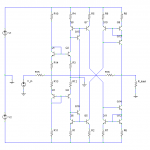
Here is another idea, don't know if this will really work that well or not, need to simulate: (see attached diagram) might be a starting point anyway
OH! Almost forgot, I routinely get 100x current gains using vacuum tube current mirrors. 5829 diode(3 in series) and 9KC6 pentode Works quite nice.
Mr Evil,
I need to do some research on current mirror configurations I think, to understand the circuit now. Maybe Q13 and Q14 bases should be just connected to a fixed voltage like a standard cascode? Just want to freeze the collector voltages on Q9 and Q12 so the mirror transistors operate under identical conditions, so maybe will match better to avoid distortion. Undoubtedly, the last output stage is the most likely to give distortion problems.
Hi Jan,
I think you mentioned some AD... chip once that used current conveyors. Fun coming up with unusual ideas anyway. Might even work sometimes.
Hi X.G.,
Say, that CZ-1 schematic shure does look similar! We should check on those strange current mirrors they used, maybe they have current gain.
Don
True enough, trying to find a large transistor with identical properties to a small one looks unlikely, but how about we make one:
The super matched transistors like the MAT01 ...04 series use an array of identical small transistors with half and half wired in parallel to make two larger transistors. We just need some micro-gremlin to go in there and chop off some connections from one group to get a small one. More likely, a visit to some custom IC Fab place to make a new metalization layer for us.
Here is another idea, don't know if this will really work that well or not, need to simulate: (see attached diagram) might be a starting point anyway
OH! Almost forgot, I routinely get 100x current gains using vacuum tube current mirrors. 5829 diode(3 in series) and 9KC6 pentode Works quite nice.
Mr Evil,
I need to do some research on current mirror configurations I think, to understand the circuit now. Maybe Q13 and Q14 bases should be just connected to a fixed voltage like a standard cascode? Just want to freeze the collector voltages on Q9 and Q12 so the mirror transistors operate under identical conditions, so maybe will match better to avoid distortion. Undoubtedly, the last output stage is the most likely to give distortion problems.
Hi Jan,
I think you mentioned some AD... chip once that used current conveyors. Fun coming up with unusual ideas anyway. Might even work sometimes.
Hi X.G.,
Say, that CZ-1 schematic shure does look similar! We should check on those strange current mirrors they used, maybe they have current gain.
Don
Attachments
- Status
- This old topic is closed. If you want to reopen this topic, contact a moderator using the "Report Post" button.
- Home
- Amplifiers
- Solid State
- How to cancel odd order harmonics?