Certainly it's easy enough to achieve such an effect, and Iinvented two of them - one which injects current into the base
of the output all the time, and another which was the one I
patented in 1976. I didn't choose to use the former, but I
noticed later that Technics picked it up in one of their amps.
I didn't use it because like the SAE design, the output devices
remained on, but the signal passed through diodes that did
switch on and off, so you couldn't argue that the signal actually
passed through devices all of which were always forward biased.
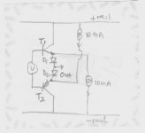
Is your first idea looks like this, Mr. Pass? I never built the prototype, because I also think that the finals can be non-turnoff, but the diodes will turn off.
Attachments
smoking-amp said:Any mirror designs around that get really large current gains, like 50 or 100?
This is my High-Scale Current Mirror.
An externally hosted image should be here but it was not working when we last tested it.
An externally hosted image should be here but it was not working when we last tested it.
The scale ratio of this one is about 50.
An externally hosted image should be here but it was not working when we last tested it.
An externally hosted image should be here but it was not working when we last tested it.
The scale ratio of this one is about 200.
I have studied to use such Current Mirror on power amp for several months.
Re: Error Correcting Magnifying Current Mirror
Did you see it?
(from http://www.essex.ac.uk/ese/research.../J6 Low distortion programmable gain cell.pdf)
smoking-amp said:My first shot at an error correcting high magnification current mirror is attached. Q
Don
Did you see it?
(from http://www.essex.ac.uk/ese/research.../J6 Low distortion programmable gain cell.pdf)
Attachments
Our Cup Runneth Over!
re: wensan and xocoatl
Wow, now we have a bonanza of high gain/ high current mirrors.
Anyone have any typical distortion figures for these? This capability could really change the picture for amplifier designs. ( wild visions of composite V-I output amplifiers with ppm or better distortion figures racing thru my mind, or maybe low feedback amplifiers with good distortion figures too)
Perhaps, the long lost voltage mirror stage can be tackled in a practical way, finally, with some of these ideas too.
Don (who is freezing up in Maine at the moment)
I've played with all of these current-mirrors-with-gain on the end of the amp I've been working on here, but to be honest the simulations suggest that none of them are as good (in terms of distortion) as a plain old emitter follower stuck on a normal current mirror.
Some improvement to quiescent stability of the emitter follower can be had by partially feeding back the output current through a split emitter degeneration resistor, making it almost a current mirror, but even small values have a big impact on distortion.
Some improvement to quiescent stability of the emitter follower can be had by partially feeding back the output current through a split emitter degeneration resistor, making it almost a current mirror, but even small values have a big impact on distortion.
Re: Our Cup Runneth Over!
This is the distortion figure that I simulate.
The scale ratio of Current Mirror is 200.
The 2nd and 3rd harmonic distortion less than 1%.
smoking-amp said:re: wensan and xocoatl
Wow, now we have a bonanza of high gain/ high current mirrors.
Anyone have any typical distortion figures for these? This capability could really change the picture for amplifier designs. ( wild visions of composite V-I output amplifiers with ppm or better distortion figures racing thru my mind, or maybe low feedback amplifiers with good distortion figures too)
Perhaps, the long lost voltage mirror stage can be tackled in a practical way, finally, with some of these ideas too.
Don (who is freezing up in Maine at the moment)
This is the distortion figure that I simulate.
The scale ratio of Current Mirror is 200.
The 2nd and 3rd harmonic distortion less than 1%.
An externally hosted image should be here but it was not working when we last tested it.
The scale ratio of Current Mirror is 50.
R3, R4 change to 50 ohm and 1 ohm.
An externally hosted image should be here but it was not working when we last tested it.
An externally hosted image should be here but it was not working when we last tested it.
R3, R4 change to 50 ohm and 1 ohm.
An externally hosted image should be here but it was not working when we last tested it.
An externally hosted image should be here but it was not working when we last tested it.
How about this one?
To weigh gains and losses,
The solution like this is good enough!
An externally hosted image should be here but it was not working when we last tested it.
An externally hosted image should be here but it was not working when we last tested it.
To weigh gains and losses,
The solution like this is good enough!
Re: warning
Yes, It's wrong. This is SLC circuit.
Do you have AES paper of SLC ?
X.G. said:
I am not convinced of the CZ-1 sch of my post is correct,cause they are from the Chinese magazine which sometimes make errors....in my eyes,the current mirror circuit of it is wrong!

Yes, It's wrong. This is SLC circuit.
Do you have AES paper of SLC ?
Attachments
Re: Re: warning
yes....your circuit should be right and work correctly,and the circuit which I post do not work in the Pioneer theory.
thank for your correct.........send me a Email,pls
X.G.
SkyChu said:
Yes, It's wrong. This is SLC circuit.
Do you have AES paper of SLC ?
yes....your circuit should be right and work correctly,and the circuit which I post do not work in the Pioneer theory.
thank for your correct.........send me a Email,pls
X.G.
Differential current amp
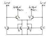
Finally found the article in my files. This circuit is a differential current amplifier that was in an opamp circuit by Mr. Rudy J. Van De Plassche in the Dec 71 IEEE JSSC. He used it as the load on a folded cascode LTP. It consists basically of two Wilson current mirrors with the diode in common. It has a current gain of beta.
Regards,
Ray
- Status
- This old topic is closed. If you want to reopen this topic, contact a moderator using the "Report Post" button.
- Home
- Amplifiers
- Solid State
- How to cancel odd order harmonics?