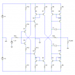
After looking at the circuits mentioned above, here is another improvement. The biasing for the input stage is now changed (is there a special name for that configuration? I see it quite a lot), yielding even lower distortion. Also shown is dominant pole frequency compensation across the output stage. That can be done away with if there is a lot of degeneration in the input stage, trading distortion for slew rate.
I would expect a normal cascode to behave similarly, since Q13/Q14 bases are already connected to what is effectively a constant voltage. The Wilson current mirror just uses the minimum of components, plus it gives the maximum possible output swing, plus they compensate for base currents of the other two transistorssmoking-amp said:...Maybe Q13 and Q14 bases should be just connected to a fixed voltage like a standard cascode? Just want to freeze the collector voltages on Q9 and Q12 so the mirror transistors operate under identical conditions, so maybe will match better to avoid distortion. Undoubtedly, the last output stage is the most likely to give distortion problems...
Attachments
improved magnifying mirror maybe
My last mirror with gain circuit attempt suffers from unmatched currents in the base - emitter junctions of the high current transistor and one of the "diode" emulators.
So here is another approach that only has one junction pair to match up. Q1 and Q2 need to be matched, Q3 should be capable of the higher output current and have a reasonably constant current gain: Beta
With the emitter resistors proportioned as shown, when Iout is Beta x Iin, then Q1 and Q2 operate with identical conditions, so hopefully distortions will cancel out.
Don
Attachments
??
Bricolo, ""Won't this "break" the simmetry in the diff pair?""
Are you referring to the "magnifyingmirror" circuit?
If Q1 and Q2 emitters have the same voltage on them, then the currents thru the emitter resistors must be in proportion to 1/R and 1/B*R. Since Q3 will be providing approx.I= B*Iq2, it will be providing most of the current thru R, leaving just Iq2 = Iq1 for Q2 to handle (will have to tweek resistor values slightly to compensate for base current losses until Iq2 = Iq1).
So a trimpot in the circuit would be helpful to tweek one of the resistors while watching a distortion analyzer on the output, with an applied sinusoidal input current. Final result is to get both Q1 and Q2 to operate under identical conditions. Putting a cascode stage on the output would be useful to pin Q2's collector voltage to the same value as Q1's collector.
(another way to view circuit operation is to split the R resistor into a B*R value on Q2 emitter, and a slightly less than R resistor on Q3 collector. Tweek values of the two B*R emitter resistors until voltages on all three resistors are identical, then we can connect the Q2 emitter resistor and Q3 collector resistor back together with no effect on the circuit. So Q1 and Q2 are really operating with identical conditions despite the apparent visual dis-symmetry of the circuit.)
Of course, in reality, Q3 beta will change a little during signal swing and Q2 will provide a little feedback to Q3 base to maintain equal emitter voltages. Need to simulate the circuit to see how well distortion cancelation holds up. A more constant Q3 beta is clearly advantageous, if it were perfectly constant we could just use it in place of the magnifying mirror however. The feedback loop may do a pretty good job of compensating for Q3 beta changes. It is operating with unity gain around the Q2,Q3,R loop like an error correction scheme I think, Q2 emitter follower setting the slightly less than unity gain factor for stability. (Any error in Q2 current versus Q1 current is fixed by Q3 with just the right forward gain to fix the problem exactly. )
Don
OH! OK
Start with the usual simple unity gain current mirror where both sides are identical. Now hang some more identical transistors in parallel on one side. The same base - emitter voltage makes them each contribute the same current to the output as the original output transistor. Paralleling the transistors this way is equivalent to just using a larger (but identical characteristics) transistor. Of course, this only goes so far before too many parallel transistors would start to drag down the base - emitter voltage by loading from base currents. So high beta transistors are preferred.
It is possible to build current mirrors from MosFets too, though a little more difficult to match. In this case the gates would not load down the gate voltage (except AC wise from capacitance).
I like my new magnifying mirror circuit approach even better than this conventional paralleling approach, I am hoping it works well for distortion correction. Have to simulate yet.
Don
This new thread seems is a working example of what we are talking about
http://www.diyaudio.com/forums/showthread.php?s=&threadid=50083
http://www.diyaudio.com/forums/showthread.php?s=&threadid=50083
Hi Luminauw,
Yes, similar topology, but I don't think any of these are using current mirrors with gain, just conventional current mirrors to get current from the V rail directions. (The CZ-1 mirrors look like unity gain too.)
Bricolo,
I forgot to mention, for the case where emitter resistors are used in the current mirror circuit, the paralleling scheme would require paralleling equivalent emitter resistors for each added transistor. So net effect is that the output transistor emitter resistor gets lowered in value by the gain factor.
lumanauw said:This new thread seems is a working example of what we are talking about
http://www.diyaudio.com/forums/showthread.php?s=&threadid=50083
hi, lumanauw
I follow you.Personly,I think the JR-9 topology (if the sch is correct) is basically similar to the Pioneer CZ-1/MZ-1,and IIRC the CZ-1/MZ-1 made in 1979.
In the CZ-1/MZ-1 sch,the V/I stage and I/V stage are very clear.but I cannot get that in 'JR-9'

BTW:I am interested in the first drive stage of the 'JR-9 sch' which idea maybe very good.
PS:I am also interestd in the power output stage of a Japanese very expensive power amp,which have non-emitter-resister, applying current mirror technology.
X.G.
smoking-amp,
sorry but we misunderstood. I know what a current miror is, and how current mirors with gain work (I just didn't know this name)
my question was related to what D. Self said: a current mismatch in the diff pair leads to distortion.
the aim of your current miror is clearly to unbalance the diff pair, I don't see the need for this, that's what I asked.
Bricolo,
Now I am the one who is not understanding. I agree with D. Self's statement about unbalancing a diff. pair producing distortion. But what diff. pair are you speaking of, on the amplifier input? If I were to use a diff. pair input stage followed by current mirrors with gain, I would use current mirrors with gain on both diff. amp. stage outputs. Essentially acting like the VAS gain stage but getting gain from linear current gain instead. No imbalance of the diff. amp. stage would be necessary.
OH! Now I think I am getting the picture you are seeing. A diff. amp. input with current mirror on one output, with the output for the VAS taken from a connection of the mirror output and the 2nd diff. ampl. output tied together. Yes, this would not be a good topology using a mirror with gain. Need to apply the same gains to both diff. ampl. outputs. I would use a dual/complementary diff. ampl. input (NPN and PNP diff. amps.) with each one driving a current mirror with gain at the opposite rail. Then connect the current mirror outputs together to act as a symetrical VAS similar to Mr. Evil's output stage, or the CZ-1 mirror setup.
Don
warning
Hi,smoking-amp
I am not convinced of the CZ-1 sch of my post is correct,cause they are from the Chinese magazine which sometimes make errors ....in my eyes,the current mirror circuit of it is wrong!
 ...The AES paper(super linear circuit,the 66th convention 1980 may 6) which wrote by Pioneer engineer don't show the details of that.
cheers
X.G.
smoking-amp said:or the CZ-1 mirror setup.
Hi,smoking-amp
I am not convinced of the CZ-1 sch of my post is correct,cause they are from the Chinese magazine which sometimes make errors
....in my eyes,the current mirror circuit of it is wrong! ...The AES paper(super linear circuit,the 66th convention 1980 may 6) which wrote by Pioneer engineer don't show the details of that. cheers
X.G.
Indeed, we're thinking of something different. In the circuit you posted, the current mirror is not used as a gain stage. What we want is to use current mirrors to provide gain, since they have inherent distortion cancellation.Bricolo said:I think we were not talking about the same design
Here's what I was thinking about, the right wire goes to VAS
That's where I can't see the use for an assymetric current miror
The problem is that a normal current mirror can only provide voltage gain, as in the circuits I have posted. This is fine for low current applications, but for more general purpose use there must be current gain in the last stage.
This could be done by adding a standard emitter-follower output stage, but that would add some distortion, defeating the point of doing this in the first place. Thus smoking-amp is considering ways that a current mirror could be altered to provide current gain while still keeping the distortion cancellation.
Mr Evil said:
Indeed, we're thinking of something different. In the circuit you posted, the current mirror is not used as a gain stage. What we want is to use current mirrors to provide gain, since they have inherent distortion cancellation.
The problem is that a normal current mirror can only provide voltage gain, as in the circuits I have posted. This is fine for low current applications, but for more general purpose use there must be current gain in the last stage.
This could be done by adding a standard emitter-follower output stage, but that would add some distortion, defeating the point of doing this in the first place. Thus smoking-amp is considering ways that a current mirror could be altered to provide current gain while still keeping the distortion cancellation.
You can have a current mirror with gain by giving them unequal emitter resistors, if you use those.
Another way is to say duplicate the output part of the mirror, with the collectors connected. Current gain = 2 in this case.
Jan Didden
Mr Evil said:
Indeed, we're thinking of something different. In the circuit you posted, the current mirror is not used as a gain stage. What we want is to use current mirrors to provide gain, since they have inherent distortion cancellation.
The problem is that a normal current mirror can only provide voltage gain, as in the circuits I have posted. This is fine for low current applications, but for more general purpose use there must be current gain in the last stage.
This could be done by adding a standard emitter-follower output stage, but that would add some distortion, defeating the point of doing this in the first place. Thus smoking-amp is considering ways that a current mirror could be altered to provide current gain while still keeping the distortion cancellation.
OK I'll have to have a deeper look on the topology you and smoking amp were talking about
Can someone post a "full" schematic, just to be sure I don't misunderstand?
Are you telling that assymetrical current mirors can be used to obtain gain, and produce less distortion than a common emitter gain stage?
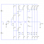
I've attached a modified version of the circuit I posted earlier, with an asymmetrical current mirror output stage as per janneman's suggestion. If the emitter resistors are equal, then the current gain is approximately three. Unequal emitter resistors could increase current gain to more practical levels (I suppose at least 10 would be needed for most applications, and at least 100 for a power amp).Bricolo said:OK I'll have to have a deeper look on the topology you and smoking amp were talking about
Can someone post a "full" schematic, just to be sure I don't misunderstand?..
Theoretically, a current mirror has perfect distortion cancellation. Asymmetry is going to harm that, but it is possible that such a current mirror could yield very low distortion. How low remains to be seen.Bricolo said:...Are you telling that assymetrical current mirors can be used to obtain gain, and produce less distortion than a common emitter gain stage?
More simulation and eventually building and testing are necessary to see just what is possible, but so far it looks to me like this topology potentially has significantly lower distortion than conventional designs, without many compromises in other areas.
Attachments
While it's easy to cancel 2nd harmonic to a large extent using
a symmetric circuit, it's much more difficult to cancel higher
order types without recourse to some sort of feedback.
In the case of 3rd harmonic in an output stage, we usually
see "compression", of which clipping is the most extreme
example. For this I can imagine a cancellation scenario
using complementary Mosfet output followers and taking
advantage of the increased transconductance at higher currents
to offset this. It would require quite a bit of tweaking, though,
and I'm not sure the results would be particularly worth it.
- Status
- This old topic is closed. If you want to reopen this topic, contact a moderator using the "Report Post" button.
- Home
- Amplifiers
- Solid State
- How to cancel odd order harmonics?