Hi All
I am new to this forum but have been browsing for a while and see that there are some very experienced and knowledgeable girls and boys kicking around, I am very humbled!!
I am very interested in this AMZ Mini Booster, FET based guitar preamp/booster circuit…
AMZ Mini Booster
But I wondered if you clever guys and girls could help me. Am I correct in assuming that the input impedance of this circuit is 1.0MOhm as set by R1? But what is the output impedance, I am thinking this is 100KOhms as set by the pot R6? Is this so and if so, what would be the impedance without the pot?
I am basically trying to find a simple FET based buffer/preamp to go between my acoustic guitar Piezo pickup and the line input of a mixer (not a guitar amp that this circuit is designed to drive). I tried the simple common source circuit here…
Common Source FET buffer
Great sound, but not enough gain to drive the mixer’s line input. So I discovered the AMZ Mini Booster circuit above. This looks like the gain will not be a problem, but the output impedance could be too high and it may colour the sound a little too much (I am willing to try it however). My basic requirement is an input of 1.0Meg and output to match a 20K input impedance line level mixer input. The maximum output voltage of the piezo pickup is around 1.0V rms under hard playing conditions. I love the simple sound you get with FETs and so would really like a one or two FET circuit for the job
Any help or advice you can give on the circuit(s) would be much appreciated
Cheers
Ray
You might check out a thread for FET-based electric guitar preamps. It's a fairly long thread, but it has lots of good meat in it. You can find it at:
http://www.diyaudio.com/forums/showthread.php?threadid=27524
Different individual FETs can have very different characteristics. These will require different values in the circuit. The thread has information about how to measure the characteristics of your FETs and adjust the values of the rest of the circuit.
Piezo pickups normally have a fairly high-level output, and shouldn't need much boost if you have the impedence high enough. They require a very high impedence input. The Rane AP-13's piezo input had an impedence of 5 Megohm. You may find better results with the piezo by increasing the input impedence.
-Vance
Hi Pete
Thanks for your reply from Down Under, i'ts appreciated!
I always thought that you needed an output to be 5 to 10x lower impedance than the load you are driving and that a high impedance output into a lower impedance load was not good. My knowledge is not too good however! Can you confirm as if I am wrong, this is good news!
Incidentally is the output of the mini booster 100K as I expected and could you tell me what the impedance would be without the pot?
Cheers
Ray
MondyT said:Hi Pete
Thanks for your reply from Down Under, i'ts appreciated!
I always thought that you needed an output to be 5 to 10x lower impedance than the load you are driving and that a high impedance output into a lower impedance load was not good. My knowledge is not too good however! Can you confirm as if I am wrong, this is good news!
No, you are right - he was wrong - although I suspect it was more a typing error than anything else.
Incidentally is the output of the mini booster 100K as I expected and could you tell me what the impedance would be without the pot?
I wouldn't have a clue how to calculate it, the constant current load messes it up rather a lot - but with a 100K pot on the output you really need a guitar type input to feed it to, not a line input.
If I wanted to know, I'd remove the output pot, and measure the output impedance.
If you're wanting to drive a line input, I would suggest adding an emitter or source follower on the output.
Pete, don’t worry my friend, I got it the wrong way round myself when writing my reply. I had to read it about 4 times until I was sure I had all “inputs” and “outputs” in the right order. And it is about -4deg.C here in the UK so I have no excuse!!
Vance, thanks for your reply and the link, this was the link were I originally found reference to the Mini-Booster circuit that I thought my be close to what I need. For some unknown reason I failed to notice there was more than just one page of threads and thought it finished on page one! A good read with most of it going over my head, but when I get time to study this link I hope to gain a little more insight in to FETs. Nigel has kindly pointed out what I feared would be the case for driving a 20Kohm line input, but I am not sure where to go from the first FET stage and I have no idea how to measure the output impedance of the Mini-Booster without the 100K pot!
Now JP Hudlsey’s schematic at the end of post #109 of this thread here…
JP Hudlsey’s schematic
seems to be very close to what I am looking for but I do not think the EQ section will be of any benefit to an acoustic guitar and so I would need to remove this. Could anyone tell me if I can use this circuit but just connect Q1 Drain Direct to the coupling cap C5, will this remove the EQ section? Also JP states the output impedance of the circuit Emitter-Follower is around 200R, so would it be possible to replace the 250K guitar pot on the output with say, a 5K pot to provide a better match to my 20KOhm input? Finally will this circuit then provide enough gain (with the emitter-follower just acting as a buffer) and is there a FET version of an emitter follower for the output as I would really like to keep the circuit all FET based if at all possible?
Once again, thanks all for your replies it is really appreciated here
Cheers
Ray
Hi All
Still searching!!
I found a two stage FET preamp idea that looks extremely close to what I need here....
Two Stage FET Preamp
Now this looks close but as always I wonder if the gurus here could answer a couple of questions before I commence obtaining some bits to try the circuit out (Credit crunch impoverished right now so need to get it mostly right before spending!)
1. Would I have to change any component values, resistors, FETs etc, for a 9v battery supply?
2. I am not sure, but it looks like this circuit may be a little too power hungry for 9v PP3 battery operation. Can anyone calculate the circuit current consumption, and if it is too high, can the circuit be modified for lower power consumption?
3. The input impedance is perfect, but as usual I need to drive a 20K load. I *think* the circuit output impedance without the pot is 1200R?? Is this the case and if so could I say use a 4.7K pot for the output, thus looking better for the 20K load without upsetting the circuit or causing problems?
I hope you guys can help coz I think this is about as close as I can get to what I think I need
Cheers
Ray
[
The input impedance is perfect, but as usual I need to drive a 20K load. I *think* the circuit output impedance without the pot is 1200R?? Is this the case and if so could I say use a 4.7K pot for the output, thus looking better for the 20K load without upsetting the circuit or causing problems?
hello.
the output impedance should be around 1200ohm i think too.
i would not worry about that 10k pot,because some hifi-amps have 20k inputimpedance and use a 10k(alps)pot.
greetings.............
Thanks mjf, appreciated
8mA is a little higher than I was hoping for but should be just OK on a small 9v battery.
If I add a capacitor across the FET source resistor doesn't the gain increase at the expense of a flat frequency response? I have read it somewhere that 100uF or so should be used here to ensure good low frequency response using a bypass cap. I will have to try this as I would love to have enough gain with just the one FET as I want to keep the preamp as simple and as clean as possible, as well as keep the battery life good. This is why I would prefer to use a discrete based circuit rather than an Op-Amp as Minion suggested. To me it just fits better with acoustic guitars!
If I used 100uF as a bypass cap, I may have too low a response and invite a boomy sound or low end feedback problems with the acoustic guitar? I suppose the only way to find out is too try it. Will say a 10uF to 100uF cap here upset the flat response of the amplification too any serious extent?
Cheers
Ray
yes,i would try it with 10uf and later on with 100uf and listen to it.if 100uf is too boomy and 10uf too poor,try 47uf and so on.because this amps have to fit to your special guitar(equipment).it is a question of sound,because some like it a little bit 'boomy',some do not.
greetings...........
greetings...........
MondyT said:
I will have to try this as I would love to have enough gain with just the one FET as I want to keep the preamp as simple and as clean as possible, as well as keep the battery life good. This is why I would prefer to use a discrete based circuit rather than an Op-Amp as Minion suggested. To me it just fits better with acoustic guitars!
So you're not wanting it 'clean', you're wanting to add distortion and lower the quality - an opamp based design will be far 'cleaner', and make the guitar sound more accurate.
If I used 100uF as a bypass cap, I may have too low a response and invite a boomy sound or low end feedback problems with the acoustic guitar? I suppose the only way to find out is too try it. Will say a 10uF to 100uF cap here upset the flat response of the amplification too any serious extent?
It doesn't affect the 'flat' response at all, using a smaller capacitor will provide bass roll-off, but no matter how large you make it, it can't go any higher than completely flat.
Bear in mind all the capacitor does is remove negative feedback, so it will increase distortion considerably, and reduce frequency response, not just increase the gain.
Thanks for your reply Nigel
Rats!! your reply has really thrown me into a turmoil, and I was having a hard time deciding where to go as it was!!
I liked the idea of the FETs sounding akin to a tube input stage but this maybe better for electric guitar pickups rather than piezo transducers used in acoustic pickups. I am just going on my Google research, most guitarists that use these simple FET circuits seem to swear by them. There is any number of acoustic preamps on the market but most of these have higher input impedance and cost a fortune for what they are. I liked the idea of a very simple circuit and the fact that I could make it my self (by the time you have bought all the bits + case etc and all the bits for trials and experiments, I would think you would not be too far off commercial preamp costs, but that is not the point!)
I did not think that the simple common source FET circuits would introduce any distortion by their nature. I was hoping to be able to use this circuit config without a bypass cap but the gain is not quite sufficient. I do not understand the principles of negative feedback really (not good, I know!) but I thought the common source FET circuit did not use feedback as there seems to be no connection from the output back into the input, but as I said I have not really got a clue here!
Do you have any links to a (simple!) FET (or other) op-amp based circuit that I could try as it looks like I may have to build both and compare the sound? I suppose the concrete parameters I require are a 1.0M input and low output impedance suitable to drive guitar cables and a 20K line input on a mixer. Ideally low power consumption and low distortion are also desired? I do not need any EQ or tone shaping as I intend to do all this from the mixer at line level. I just need a “nice” sounding gain stage
Ooh the confusion!!
Can anyone help me here!
Cheers
Ray
MondyT said:Thanks for your reply Nigel
Rats!! your reply has really thrown me into a turmoil, and I was having a hard time deciding where to go as it was!!
I liked the idea of the FETs sounding akin to a tube input stage but this maybe better for electric guitar pickups rather than piezo transducers used in acoustic pickups. I am just going on my Google research, most guitarists that use these simple FET circuits seem to swear by them. There is any number of acoustic preamps on the market but most of these have higher input impedance and cost a fortune for what they are. I liked the idea of a very simple circuit and the fact that I could make it my self (by the time you have bought all the bits + case etc and all the bits for trials and experiments, I would think you would not be too far off commercial preamp costs, but that is not the point!)
Generally guitarists aren't after 'quality' they are after a specific 'sound' - which normally means frequency limited, and distorted.
I did not think that the simple common source FET circuits would introduce any distortion by their nature. I was hoping to be able to use this circuit config without a bypass cap but the gain is not quite sufficient. I do not understand the principles of negative feedback really (not good, I know!) but I thought the common source FET circuit did not use feedback as there seems to be no connection from the output back into the input, but as I said I have not really got a clue here!
The resistor in the source gives negative feedback (as well as setting the bias), bypassing it increases the gain, at the expense of higher distortion. It works identically with valcves and transistors as well.
Do you have any links to a (simple!) FET (or other) op-amp based circuit that I could try as it looks like I may have to build both and compare the sound? I suppose the concrete parameters I require are a 1.0M input and low output impedance suitable to drive guitar cables and a 20K line input on a mixer. Ideally low power consumption and low distortion are also desired? I do not need any EQ or tone shaping as I intend to do all this from the mixer at line level. I just need a “nice” sounding gain stage
It's easy to make a 1Meg input impedance opamp design with a low impedance output (just a single non-inverting stage, using a FET input amp - like a Texas TL0xx series).
Throw one together and try how you like the sound, it also means it's VERY easy to adjust it's gain with no other unwanted effects. This is how most active guitars and preamps work.
Have you considered just using a ready made active DI box?, you may be surprised how good they sound - and it does essentially what you're wanting
hello mondyt.
don`t worry about "technical discussion".
without a bypasscap the voltagegain is low,round about 1,5times.
with this it can go up to about 4times,i think.
if it is to loud after that,you can add a res in series to the cap........so you can fit the preamp`s gain to your mixer.if that result is not good to your ear,you will find annother amp.but there is a good chance that it will work.
i think many guitarists prefer this amp over an opamp because it is a single-ended class a............
greetings............
MondyT said:Do you have any links to a (simple!) FET (or other) op-amp based circuit that I could try as it looks like I may have to build both and compare the sound? I suppose the concrete parameters I require are a 1.0M input and low output impedance suitable to drive guitar cables and a 20K line input on a mixer. Ideally low power consumption and low distortion are also desired? I do not need any EQ or tone shaping as I intend to do all this from the mixer at line level. I just need a “nice” sounding gain stage
Ooh the confusion!!
Can anyone help me here!
Cheers
Ray
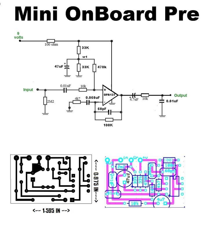
Here is a simple Curcuit and PCB i designed (If you can call it that as it is just the basic implementaion of an opamp) that I use as active electronics in my Electric Guitar...It has 2m2 Input impedance and low output impedance and runs off of a 9v battery and I used an OPA132 but any Single Fet opamp should work....If you want the gain adjustable use a pot instead of the 100K resistor in the feedback loop...The PCB is small enough to hide in most instruments and best of all it it sounds great ( at least in every guitar and bass I have installed them in)....
Cheers
Ray,
I think that your assumptions are wrong from the very beginning. As Vince stated, the piezo pickup has very high output impedance (5Meg or more). You mention also that the signal from piezo tranducer can be even 1V. How it is possible that this is not enough for a mixer input?
The AMZ booster that you mentioned in the beginning of this thread has gain ~500 (it is based on National Semiconductor application note). You can build it if you want to have a distored signal.
You need a preamp with at least 5-8MOhms (or more) input impedance. You can build the the preamp designed by Minion (with increased input resistor and added filtering capacitor after the 100 Ohms resistor), or build Hugsley preamp (without the filter between stages), or the Common Source FET buffer.
If you search this forum for "piezo preamp" phrase, you will get a plenty results.
I built the Hugsley preamp but I haven't tested it with piezo pickup. But I think that it should work correctly assuming you increase the input resistor.
You may also take a look at Carvin's piezo module: http://www.carvinmuseum.com/pdf/guitarbass/503a-activepiezomodule.pdf or check Artec piezo preamps which are quite good and not that expensive.
Mark
- Status
- This old topic is closed. If you want to reopen this topic, contact a moderator using the "Report Post" button.
- Home
- Live Sound
- Instruments and Amps
- FET based Acoustic preamp help