Good evening, how to modify the project vellman to run in 45 /-45v
project: page 18
http://www.vellemanusa.com/downloads/0/illustrated/illustrated_assembly_manual_k8060_rev1.pdf
project: page 18
http://www.vellemanusa.com/downloads/0/illustrated/illustrated_assembly_manual_k8060_rev1.pdf
Replace Vas transistor, the BC639 by a BD 140 and include more two output transistors
in parallel with the ones you already have... each one of the added power transistors must have their own emitter resistance and the base to colector capacitor,
Adjust the current to read 1 milivolt over each one of your emitter resistance.
After adjust be sure you do not have alternated voltage into the output, check with your multimeter into the AC scale....normally when you have alternated voltage when your amplifier is iddle and no signal entering seems you have oscilations..and those transistors, made for switching purposes, are addicted to oscilate a lot.... when we have oscilations we also have trouble to adjust stand by current to a low level..oscilations turns everything into a big mess and we just cannot adjust low current during oscilations....so.... if you can adjust, seems you have not oscilations.
The amplifier uses bootstrapp, sounds great.... the good topologie....the bad thing is exactly this output darlington..there's the weak point..the source of trouble you gonna have during it's lifetime.
Good luck
regards,
Carlos
............................................................................................................................................
But a real good idea, to provide you reliability, is to modify deeply the circuit..removing the output darlington one and substituting them by a traditional emitter follower, a driver and a power transistor to each rail, following Doctor Self book suggestions.... those TIP142 will be a problem to you..i ensure you that they will bother you more than once.
Last edited:
I was thinking about.... this was an assassination of output, the voltage used
to use a single pair of TIP142/147, the maximum supply voltage should be 26 volts positive and 26 volts negative.... because will produce 65 watts RMS into 4 ohms.... and when producing this audio power will be dissipating 100 watts into the transistor case (beeing seriously optimistic..more real value is 75 watts of maximum continuous power dissipation)
So, i think safe to use a single pair is 26 volts maximum to each rail, and you gonna have around 40 watts rms into 8 ohms and 65 watts rms into 4 ohms.
Using 40 volts you largely exceed the limit...i think Mr Veleman made a mistake, or he was supposing you gonna use only 8 ohms loads (exclusive load)..and even this way the amplifier should blow the output when reproducing continuous tones into clipping mode.
To operate using 45 volts positive and 45 volts negative you need huge power transistors, as your power will be higher than 130 watts of audio power into 4 ohms... and while having that power into the speaker you gonna be dissipating almost the maximum power a huge transistor, alike 2SC5200 and 2SA1943 can hold...so... you will be touching the dissipation limits if your amplifier works continuously with a steady tone, or full volume, or a sinthetizer injecting continuous sinusoidal or any complex waveform in a continuous mode.... even using 45 volts, the more safe thing to do is to use tow pairs of 2SC5200 together the PNP counterpart that is 2SA1943 (or 1946, i do not remember..you check if you want it).
I transistor TIP142 dissipates, optimistically speaking, 100 watts... realistic, something between 75 and 85 watts (heat, total heat, not audio power...audio power is 35 percent less than that).... the 2SC5200, optimistically dissipates 150 watts (specification is 200-250 watts, but this is artificially forced to stay at 25 degrées centigrades into the junction and this does not happens into real life)..... one 2SC5200 dissipates (real world) almost twice compared to the TIP142... also the 2SC5200 can manage to operate with much more colector to emitter current and also can hold much more voltage...the maximum frequency operation is also much bigger than the TIP142.
The use TIP142 is to reduce board size, to make it economicall, to sell it cheap.... but really, i cannot understand...really i cannot, how they suggested to use 40 volts... this is a big mistake or a criminal thing.
Well...maybe i have not understood the point....yeah..maybe i am wrong.
regards,
Carlos
Using two output pairs..the ones provided and another extra pair
You will be safe using supply voltages that goes maximum at 38 volts simetrical...or 38 volts positive and 38 volts negative.
Under such conditions you gonna have around 130 to 140 watts of power into 4 ohms...and you gonna be reaching the power transistor maximum dissipation...will be safe this way...in special if you use 8 ohms speaker or 6 ohms speaker when your power will be 70 to 85 watts rms.
Maybe they painted the 40 volts values thinking the supplies people find have enormous drop of voltage during operation....but really, drops from 40 to 26 volts is too much...some mistake really happened.... because with the original single pair the maximum voltage is 26 volts and maximum ouput power (safe) is 60 to 70 watts rms (4 ohms of course).
Maybe there's another special TIP142 version, a bigger transistor case, able to dissipate more power in the form of heat...but not the ones show into the pdf you have attached... those ones are maximum of 100 watts..i have tested, checked many times, and i have burned several to be sure.... they were not only Morocco ones, i have tested more brands.
ST transistors...the TIP142 and TIP146 were tested here to use as serious pass output transistors in a stabilized power supply (adjustable output voltage and stabilized one..under 1 percent)...and they have melted when dissipating 70 watts..into a 29 degrees celsius environment and mounted into an enormous heatsink able to dissipate 500 watts..... Morocco ones held almost 80 watts continuous when they have melted...i have burned 7 units testing..then i give up about to you those folks.
regards,
Carlos
Last edited:
months as I did many tried but the same result even with another version
http://www.diyaudiotr.com/resim/proje/kapibara/sema.jpg
I made a card with tda7293, I found the same result, my problem that i obliged to used the transfor 2x32AC 2x ~ 45vDC
http://www.diyaudiotr.com/resim/proje/kapibara/sema.jpg
I made a card with tda7293, I found the same result, my problem that i obliged to used the transfor 2x32AC 2x ~ 45vDC
My ratings are not optimistic, as each transistor, in the reality, carries half the
heat and half the job.... the NPN amplifier side and the PNP amplifiers side works together doing the whole job...so, my ratings goes to 50 percent and are the most safe way to do this job....when you go to the component limits they use to burn, as they are specified under special conditions...the dissipation is measured while the transistor is assembled into a specially cooled block of metal that keeps the transistor case into 25 degrées celsius..and this never happens into real life.
Also..when you have a transistor that is rated to 200 watts...in real life they gonna melt when submited to this power continuously....you soon see, realise, conclude, the metal case is not enougth to transfer all that heat.
Analog sittuation is to cool a soldering iron (40 watt one) touching the small point tip into a big piece of metal... the soldering iron continues very hot and the thermal transference to the metal surface is not so big as the contact area is small... transistor heat transference (dissipation or cooling) depends how big is the contact area to the heatsink element.
Real safe, and that turns equipment really reliable, is when you double the transistor quantity to face some job... when we calculate into the limits the result is often to have shorted/burned parts.
So.... when we think into TIP142, we go to read specificatins and we see they are rated to 100 watts... more modern ratings are 125 watts... interesting they increase 25 percent the dissipation watts informed into the datasheet in those last years..inflation of dissipation watts maybe or evolution into the die to case heat transference... but...i do not believe it can face that in real life... reason why we use them with the spectation they will face half of that heat.
Velleman designers were too much optimistic, as powering the unit with a 40 volts plus 40 volts, each rail output transistor will be dissipating 115 watts into the threshold of clipping... and for sure this is above the real limits (not the specifications you read into the datasheet).... the amplifier will be able to manage 8 ohms loads in a very safe way (even during clipping) and will be into the "warning" area while operating into 4 ohms... and even 8 ohms , or 6 ohms speaker goes deep to 4 ohms or even less in some frequencies, they have some valleys of impedance because passive crossovers often used.... 150 watts rms, or sligthly higher power, is possible while using 40 volts supply, of course tollerating some clipping... and if you force the output to 10 percent of distortion, the transistor operating within the limits will for sure burn.
2 output pairs can be less unsafe... some of those amplifier survive because real music reproduction, without distortion, normal level is average.
Well....if your amplifier burns...Velleman personnel can blame the transistor factory because the amplifier will be working within the specifications range while operating into 8 ohms....but despite the theoretical game you will have, real life, burned transistors... reason why we double the transistor quantity to be safe...we double the dissipation offered to the power amplifier...we use output that can face twice the needed dissipation.
What you see in this forum..diyers that use to suggest double dissipation for safety reasons (reliability)..so..if an amplifier is to produce 100 undistorted watts... that means 150 to 165 watts of heat...then we use higher than that dissipation to the power transistors...beeing each one of them able to dissipate almost twice of that... even knowing each rail will face half of the total heat we do this way when we want the unit hundred percent safe...as the power amplifier user can force the unit to operate full continuous power using steady tones or some modern musics that have almost no average response..that goes near the peaks..compressed sounds that does not let time to the transistor to have a relief between moments they are asked to work very hard.
Amplifier users needs the amplifiers able to face 10 percent of distortion for a very long time...means the amplifier will be operating into the clipping, sucking enormous current from the supply and working much more hot than usual.... this means reliability (see Quasi power amplifier design).
Velleman amplifier operating 10 percent of distortion (real huge clipping), will dissipate 135 watts to each rail, while operating into 4 ohms having 40 plus 40 volts supply.... total dissipation will be 270 watts!
regards,
Carlos
Last edited:
Do not go thinking i dislike Velleman products..the opposite, i am a fan
I like them and a lot..unfortunatelly their design decisions were hardly influenced by costs.... resulting a not so safe (reliable) amplifier in my point of view..but watching the other side, they are beautifull and has the supply into the board, board is small and the cost is not high..... compromise between reliability and cost were the issue they faced..and they decided different than me.
Maybe they are rigth..... majority of folks does not use 4 ohms, also they do not use full power...also they do not increase volume while already distorting to reach 10 percent distortions during a long playing time...maybe the majority would be safe from problems as they will play low power.
Will not survive at my home tests..i use to play 30 minutes, full undistorted power into 4 ohms.... but this is my personal case..others are others...other use, other minds, other needs.
regards,
Carlos
Dear Orcad...that Kapibara amplifier was a development from another one
that was, in essence, not safe....... it had some thread opened to comment, and was considered not so good, OR, needing some modifications to be better.
Search the forum and you may find it.... Sakis has made comments on that thread..maybe he can inform you the thread tittle..... i did too, but i cannot remember the thread name.
regards,
Carlos
Dear Orcad 2010
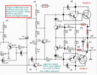
Here i am showing you simple modifications to your Velleman to make it more safe operating with 45 volts.
You just include one more output pair, increase heatsink area, install more two emitter resistances and 2 more protective sensor resistances.
You can adjust the protective resistances to reduce even more (highly suggested to do that..even to disable that "thing") the action...you can use 470 ohms or more.
Adjusting the bias, read the voltage developed over the emitter resistances..and this happens when current crosses... and try to keep it around 1 miliampere in each one of these four emitter resistances.
Use short cables, less than 12 centimeters please..to avoid oscilations..using longer cables install another 680pf capacitor, this time between base and colector of your extra transistor.
be happy!
regards,
Carlos
Attachments
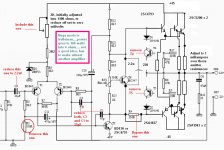
The modifications show in this schematic changes a lot of things
and makes the Velleman not more Velleman.... will loose the character and the board may become a little bit messy...this way you gonna have something alike P3A from Rodd Elliot, something alike old Aksa (basic one without secrets).... something alike several bootstrapped amplifiers including mine Dx amplifier.... and just because this way is good and made by several folks, and almost all factories since the seventies..all them have made...in our forum we had almost 8 circuits alike..almost the same...and this because the one is good..the traditional bootstrapped circuit..reliable, good sounding one.
Not a good idea to do all those modifications into the Velleman board..but this is possible without too much hard work...but needed skilled, experienced people do to that.
I really do not suggest to do all that stuff, but i am showing what will make Velleman became of of the greatest wide world amplifiers...because the topologie, not because designers... exception is Hugh Dean from Aksa...he did some evolution into the topologie...for sure he did.
Just to show you..if you wanna try..good luck..i hope you are good enought..skilled enought and lucky enought.
Velleman, i suppose, made his amplifiers to sound fine and to be cheap.... this one i am showing is to be reliable and last for your entire life and will be used by sons and grandsons if audio amplifier still gonna be used in the future.
Sorry, a mistake... R9 is 2K2
regards,
Carlos
Attachments
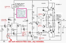
Do not remove this one..was my mistake
here is the schematic pointing the error.
Keep the resistance as original... my intention was to remove the 3K3, not this one...keep them both, more safe.
Also you may need to adjust R7 because R4 removal (jumper)
regards,
Carlos
here is the schematic pointing the error.
Keep the resistance as original... my intention was to remove the 3K3, not this one...keep them both, more safe.
Also you may need to adjust R7 because R4 removal (jumper)
regards,
Carlos
Attachments
Define "not well stabilized"... and please, show us how to stabilize
and also explain the weak points and what to do to make them strong and stable..this gonna be productive.
Do not give up before a good try.... i am sorry, but made me feel you just do not know what to do.
It is your chance to show how much you know and to teach us something
prove!.
regards,
Carlos
and also explain the weak points and what to do to make them strong and stable..this gonna be productive.
Do not give up before a good try.... i am sorry, but made me feel you just do not know what to do.
It is your chance to show how much you know and to teach us something
prove!.
regards,
Carlos
for starts
uncle charly's suggestions are give or take very correct...the bad thing that apply on perfect transistors..... tip 142-7 are not .... related cousins like bdv 66 67 will also suffer fom similar problems
if your rails where 30+30dc you got your shelf i nice amp with low power
if your rails are above 40 volts you got your shelf a ticking bomb
search for a thread called a darling.... ton story ...there you will find some info for yes and no about tip 142 147
run it in low power ....
you actually have a chance by using MJ11015-16 from ON semi ..they are by far more row bust, powerfull and reliable stil the circuit has a lot of drawbacks since ta safelly run a pair of those a ccs on the ltp, a better VAS , and a few mods on the vi limmiter is what is missing
regards sakis
- Status
- This old topic is closed. If you want to reopen this topic, contact a moderator using the "Report Post" button.
- Home
- Amplifiers
- Solid State
- problem: project vellman!!