They control the gain...or sensitivity.... also the lowest tone the amplifier can
reproduce without losses.
Richie00boy is really English.... what he said is perfect..but very technicall..something "by appointment from her Majesty, the Queen!".... lovely those "englanders".....pomp and circumstance.
The smaller capacitor, installed in parallel, is there to avoid the resistance we may have when high frequencies (oscilations) will be send to ground througth those condensers..they are coiled inside.... construction is alike a coil, so, they have inductances too, not only capacitances and some resistance (leakage)... the smaller capacitor in parallel represents a short to high frequencies..where the oscilations happens...offering to the circuit a "drain" of those oscilations..the smaller capacitor, not coiled, is a short to those high frequencies..reason why they are there.... "eating" oscilations as soon as they appear, not allowing them to grow and ressonate into the whole circuit...a big "throat" that gonna eat oscilations.
The bigger one, connected to ground througth the resistance.... offers to the second transistor, a different resistance from base to ground compared to the first transistor...if both had same resistance to ground the gain should be one....but doing this way, you create a gain.. a sensitivity that allow your amplifier to receive 1 volt into the input and to transform that input in 20 volts into the output..this is adjustable, this gain/sensitivity is adjustable.
The higher the resistance value, the lower the gain...of course, the inverse is also truth.
The choice of this electrolitic condenser value, the selection you gonna make there, if gonna use 22uf, 33uf, 47uf, 68uf, 100uf, 220uf, 330uf, 470uf, 1000uf ad so on, will depend the frequency you want to have your -3dB loss.... so...mine is adjusted to have 3dB loss around 5 hertz or less.... this works also with the input condenser, or capacitor...if the input block the low frequency because very small value used there..not magic is possible..you can set to flat down to 1 hertz and this frequency will not cross the very small capacitor you have into the input...so... there are some relationship with some parts into the circuit... one is selected referenced into the other.
Also R11 controls the gain..it is better to say that in advance some "perfectionist" appear to say that.
I hope this clarifies...at least i have tried hard.
regards,
Carlos
Attachments

Last edited:
Thank you Carlos. But some of your explanation is not quite correct, in particular the image is giving wrong information.
The amp goes to unity gain because at DC the capacitor is like an open circuit, so the full signal is fed back to the feedback input. At higher frequencies the capacitor is like a short circuit, so the signal is divided by the two resistors which creates gain calculated by (R11 + 1) / R12.
Having R3 and R11 the same value helps DC offset because the same voltage is dropped across each resistor by the input current of Q1 and Q2. Having them different values does not change the gain, just the offset voltage.
Sorry if this is what you meant Carlos, and I misunderstood you.
Last edited:
Will work just fine, just make sure you use a fan to cool the heatsink
I have 2 amps like this at +/-45V working fine for over 2 years. The secret is to adjust the bias properly, let the amp play music at low volume for 30 minutes then adjust the bias.
If bias is wrong then the amp will probably selfcombust.
Another secret is the small shxtty smoothing capacitors used that will give u a nice big voltage drop when the amp is on full blast")
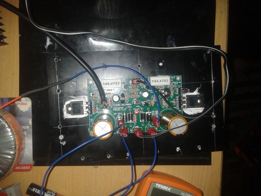
Check my amp, 2 boards on same heatsink) Works fine with temperature controlled fan (kit from Maplin)
www.forum.poweraudio.ro • Vezi subiect - Amplif welleman 100w
I have 2 amps like this at +/-45V working fine for over 2 years. The secret is to adjust the bias properly, let the amp play music at low volume for 30 minutes then adjust the bias.
If bias is wrong then the amp will probably selfcombust.
Another secret is the small shxtty smoothing capacitors used that will give u a nice big voltage drop when the amp is on full blast
Check my amp, 2 boards on same heatsink
) Works fine with temperature controlled fan (kit from Maplin)www.forum.poweraudio.ro • Vezi subiect - Amplif welleman 100w
Yeah its nice to know the amp will blow up if the bias is set wrong lol. But the bias will be set wrong when the amp is powered on the first time. Velleman state (Turn the RV1 bias adjust trimmer fully counter clockwise before applying power for the first time) I guess this is very important!!
I have not powered on the amp yet due to not having a suitable heatsink. I found assembly quite easy although I soldered some of the transistors in wrong the first time!!
At £15 pounds its rather good value I think. Iv'e already upgraded the main filter caps to Nichicon FW 4700uf as I had these laying around. I plan to test the amp with a 80VA 24-0 24-0 transformer I little less the Vellemen state but I think it will be ok.
Just found this thread and have looked through it. I have really tested the 8060 kit and it is much better than most the comments on here are saying. The phase between 10hz - 40khz only swings +/- 10 degrees. The bandwidth is also very good. Hi speed transients are great with no oscillations. Don't be afraid to try this kit.
- Status
- This old topic is closed. If you want to reopen this topic, contact a moderator using the "Report Post" button.
- Home
- Amplifiers
- Solid State
- problem: project vellman!!