
Hi!
I have one board stabilized in 5.5 volts and other in 3.31Volts. Excellent.
Will it be a big improvement if I feed the dac with two boards with 3,3 replacing the voltage regs or just keep it feeded with 5 volts only -) then it will be splited for the two 3,3 regs.
Can someone you give an opinion?
Also, if I feed the dac with two 3,3 reflektors replacing those regs, do I disconnect the 5 volts board?
Thank you.
Its a third party gear specific query. Better ask the designer of the DAC or other tweak owners. The Ref-Ds are there to serve any better split power scheme it could be possibly recommended.
Its a third party gear specific query. Better ask the designer of the DAC or other tweak owners. The Ref-Ds are there to serve any better split power scheme it could be possibly recommended.
Ok, thank you.
Thanks I thought that would be the most likely result! I wanted to be sure. I see a few folks have used reflektor d on the subbu dac, do you think it has improvement over the standard power supply? I just put together the Subbu power board and am just starting on the dac board. These are going with a shigaclone transport that is next on the project list, anyone used Salas on this transport? Thanks for the help!
Steve
Steve
Last edited:
oscillation-solved
I just wanted to share a Reflektor experience I have had, maybe this example will help someone else.
I built a 3.3VDC output Reflektor to power a Ethernet-I2S board. I did not have any 62R for the Vref, but tried 56R and got ~3.24 VDC, good enough for initial testing until I can tweak the R value with more resistors. As experiments I used a .1 uF PPS SMD cap for C1, and a organic polymer (1000uF 16V) for C2.
Everything tested fine on a dummy load, and I hooked it up to the board in a DAC set up. Now I had oscillations, whining sounds coming from the Ethernet board and around 55 mV AC reading on my DMM at the Reflektor output. On the Ethernet board there is the following at the DC input: a ferrite bead on the + input, followed by a 220uF electrolytic cap. I wondered about the ferrite... so I moved the sense wires beyond the ferrite, and soldered them to the ground and positive sides of the 220 uF cap. Bingo, everything calms right down, the oscillations are gone, and things are working well.
Just an example showing possible solutions when powering problematic circuits.
I did a long-run temperature test of my veroboard reflektorD on some scrap heatsinks I had laying around. M1 (IRF9610) and M2 (MTP3055) reached quite a bit different temperatures on identical but separate heatsinks with M1 being much hotter.
Is this normal behavior?
I didn't notice this on the PCB build but there the sinks are very close together and may heat each other up...
The output voltage remains stable and there is 0 mV AC on my DMM across the load resistor.
As I plan to use 2 separate sinks for the 5 Reflektors I'm building this is something to be considered...
Yes its normal. M1 or M2 develop their own dissipation value depending on: WM1=ICCS*(Vin-Vout). WM2=Vout*(ICCS-ILoad).
Vin is AC rectified or some direct DC feed available.
On the PCBs the board level sinks create a tunnel and are close to each other sharing some heat. There are also holes at the bottom of the PCB between them letting cooler under bottom air breathe and move up between them.
Vin is AC rectified or some direct DC feed available.
On the PCBs the board level sinks create a tunnel and are close to each other sharing some heat. There are also holes at the bottom of the PCB between them letting cooler under bottom air breathe and move up between them.
Hi,
I am building Salas Reflector D for ak4495SEQ dac: (~7V, ~33mA avg) powering only analog section.
I got some questions:
1. Since current draw is 33mA, can I use higher value of R1 e.g.: 2R5?
2. How can IDSS could be measured? or it is specific to transistor specs?
3. I use VAR 1K for R6. Is it wise to use some good quality wirewound resistors e.g.: mills instead of other metal films to lower the noise?
Please point me to thread if there are answers for those question already. Could not find it
Thanks
2R5 is good for about 240mA current limit. Plenty for your app and it will keep sinks temperature acceptable while M2 will stay well biased for spare current.
Idss of J1 can be measured by using a 9V battery, connecting a mA meter in series between (+) and D pin, G+S pins to (-). Measure it before installing it.
No, VAR is among the very best if not the very best for self noise and thermal stability expensive parts out there.
An interesting R6 alternative to listen to and judge how you like it in your application would be a Jfet like J1 in its place (see post#152).
2R5 is good for about 240mA current limit. Plenty for your app and it will keep sinks temperature acceptable while M2 will stay well biased for spare current.
Idss of J1 can be measured by using a 9V battery, connecting a mA meter in series between (+) and D pin, G+S pins to (-). Measure it before installing it.
No, VAR is among the very best if not the very best for self noise and thermal stability expensive parts out there.
An interesting R6 alternative to listen to and judge how you like it in your application would be a Jfet like J1 in its place (see post#152).
Thanks!
My crazy build will be done using schotties, 4 pole m-lytic ag+ 10000uf cap, elna silmic II 1000uf and all Var resistors (I only miss vars now). Since var resistors are sold for any desired value (at texas components) is there any way to calculate its exact value (RR) for 3,05mA idss (i just measured leakage current for my fet).
Leakage current is IGsx (gate excess current) that won't be more than 2pA until 8V Vds. What you measured is Idss most certainly. Use 47 Ohm RR for circa 3mA Idss J1. All VAR resistors are not a good investment in my opinion. Only R6. The few others can be 25ppm 1/4 or half Watt axial Dale if you insist on perfection. R1 should be a two Watt low ppm part of course.
Leakage current is IGsx (gate excess current) that won't be more than 2pA until 8V Vds. What you measured is Idss most certainly. Use 47 Ohm RR for circa 3mA Idss J1. All VAR resistors are not a good investment in my opinion. Only R6. The few others can be 25ppm 1/4 or half Watt axial Dale if you insist on perfection. R1 should be a two Watt low ppm part of course.
Thanks for explanation. I went with one var r6 and others metals. I built it. I put 3ohm on R1 (did not have 2.5). Three green LEDs. I turned it but the leds did not lit up. There is around 4v across load resistor. There is more than 10v on reservoir cap. Load resistor is geting hot after while. Is it because I used 20ohm for 7v instead of 30ohm on load. Any thoughts?
3 Ohm gives about 200mA CCS in this circuit. Your 20 Ohm dummy load demands about 350mA at 7V. Obviously mismatched. Use up to 150mA loading (no less than 47 Ohm 2W resistor test load).
Thanks for quick answer. I Put 100R 2W (I only had it around). LEDs lights up. There is 7V across resistor. Everything works. Can't wait to hook it with the dac. No it is time to sleep. Cheers and thanks again!
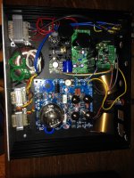
So here is my build (still work in progress):
Isolated xmos usb + ak4495 + salas reflector D (7V) powering analog left/right + placid hd 2.1 shunts + 3xTridents 3.3V (DVDD, AVDD, clocks) + lampizator Balanced SE output stage.
Previously Placid hd 2.1 was powering analog left/right 5.25V and those three local shunts
With Placid HD 2.1 it was very good, however with Salas it is damn very good, sound is more clean and stiff. It is not day/night difference, however some differences are easily noticeable right away after application:
- better transparency and blacker background
- wider bandwidth, especially highs are now more "real" and bass goes lower
- micro details are easier to pick and hear
It is not direct comparison because:
Placid HD 2.1 was 5.25V whereas Salas is 7V and ak4495 works better with higher voltages. It accepts 4.75V to 7.2V.
Placid HD 2.1 was powering analog section and whose three Trident Shunts, so some noise from shunts could be carried into analog section. Whereas Salas is powering just analog section of the dac.
Salas was build with some high quality components: Var resistors, Clarity Cap MR 0.1uF. My Placid HD 2.1 still uses trimmers for voltage and current adjustment (that could be replaced with fixed values resistors)
Considerations:
One salas could power whole ak4495. For such use three red leds could be used to give around 6.5V, which is max of what local Triedns 3.3V can accept and analog sections could be powered with 6.5V directly or maybe some local shunts from Paul Hynes could be used for powering left and right independently.
Improvements for salas board:
1. Support for four pins reservoirs capacitator. With good dual bobbin EI transformer and schottkies it is very good alternative for clumsy in use and fast draining batteries. Four pin electrolytes has much lower ESR than two pins and additionally attenuate high frequency and diodes switching noise, because the current from bridge rectifier does not go directly to board but through capacitator. I used M-Lytic AG+ 10000uF in my build.
2. Dual Positive Salas Reflector D with one common voltage reference for powering left and right channels of the analog section of the dac. Not sure if something like that is possible to build.
Improvements for salas doc:
Sections how to measure IDSS.
Sections how to apply proper dummy load. I believe some formula exists for that.
Thanks Salas. Thanks Tea-Bag. Great work! I love this regulator.
An externally hosted image should be here but it was not working when we last tested it.
Isolated xmos usb + ak4495 + salas reflector D (7V) powering analog left/right + placid hd 2.1 shunts + 3xTridents 3.3V (DVDD, AVDD, clocks) + lampizator Balanced SE output stage.
Previously Placid hd 2.1 was powering analog left/right 5.25V and those three local shunts
With Placid HD 2.1 it was very good, however with Salas it is damn very good, sound is more clean and stiff. It is not day/night difference, however some differences are easily noticeable right away after application:
- better transparency and blacker background
- wider bandwidth, especially highs are now more "real" and bass goes lower
- micro details are easier to pick and hear
It is not direct comparison because:
Placid HD 2.1 was 5.25V whereas Salas is 7V and ak4495 works better with higher voltages. It accepts 4.75V to 7.2V.
Placid HD 2.1 was powering analog section and whose three Trident Shunts, so some noise from shunts could be carried into analog section. Whereas Salas is powering just analog section of the dac.
Salas was build with some high quality components: Var resistors, Clarity Cap MR 0.1uF. My Placid HD 2.1 still uses trimmers for voltage and current adjustment (that could be replaced with fixed values resistors)
Considerations:
One salas could power whole ak4495. For such use three red leds could be used to give around 6.5V, which is max of what local Triedns 3.3V can accept and analog sections could be powered with 6.5V directly or maybe some local shunts from Paul Hynes could be used for powering left and right independently.
Improvements for salas board:
1. Support for four pins reservoirs capacitator. With good dual bobbin EI transformer and schottkies it is very good alternative for clumsy in use and fast draining batteries. Four pin electrolytes has much lower ESR than two pins and additionally attenuate high frequency and diodes switching noise, because the current from bridge rectifier does not go directly to board but through capacitator. I used M-Lytic AG+ 10000uF in my build.
2. Dual Positive Salas Reflector D with one common voltage reference for powering left and right channels of the analog section of the dac. Not sure if something like that is possible to build.
Improvements for salas doc:
Sections how to measure IDSS.
Sections how to apply proper dummy load. I believe some formula exists for that.
Thanks Salas. Thanks Tea-Bag. Great work! I love this regulator.
Attachments
Congratulations. The board has straight DC input option too as is. Its for those who already have a clean enough 5V higher than output DC line to use for input or would like to make external elaborate and expensive rectification/filtering section with 4 pole caps, LC filter choke, common mode choke, Tx snubber, diode snubber, pre-reg, whatever. Can't force expensive non widely available components as standard. The two test loads advised in the instructions work with the whole range of R1 values table there. For out that range considerations its just about the Ohm's law. J1 comes measured.
A few questions
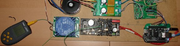
Hi! I built a Reflektor for my breaglebone black that is serving music to my dac in the same chassis ("chassis" being used liberally to describe an mdf board...).
Before using the Reflektor I powered the bbb with a 2A/5vdc smps so I could get and idea of the current draw using the music I usually play. At turn on it draws a bit over 400mA. After it stabilizes and plays the average seems to be about 350mA, with the max recorded for a two hour listening session being 410mA.
I built the Reflektor with a 1R Caddock MP930, thinking that it could draw close to 500mA, but it fell a bit short. Should I leave it as is or try to get a 1.2R instead of the 1R? I ask because the heatsinks during this two hour period stabilized at 50-51 degrees F (max was 50.7dF). It's using a 9v trafo. I live in Florida so summer is long and hot and the thing is not yet inside a case...
My second question is regarding the startup. When I hit the on button, sometimes the bbb does not start! The leds are on in the Reflektor board, but the bbb does not boot (no lights come on, as if it had no power). When I was testing the setup with smps it always started. Pulling the bbb's 5vdc plug in/out makes it start. From the measurements above it doesn't seem to drawing, even for a brief moment at startup, anywheres near the max current, so I'm not sure why this is so.
Thanks in advance.
Hi! I built a Reflektor for my breaglebone black that is serving music to my dac in the same chassis ("chassis" being used liberally to describe an mdf board...
). Before using the Reflektor I powered the bbb with a 2A/5vdc smps so I could get and idea of the current draw using the music I usually play. At turn on it draws a bit over 400mA. After it stabilizes and plays the average seems to be about 350mA, with the max recorded for a two hour listening session being 410mA.
I built the Reflektor with a 1R Caddock MP930, thinking that it could draw close to 500mA, but it fell a bit short. Should I leave it as is or try to get a 1.2R instead of the 1R? I ask because the heatsinks during this two hour period stabilized at 50-51 degrees F (max was 50.7dF). It's using a 9v trafo. I live in Florida so summer is long and hot and the thing is not yet inside a case...
My second question is regarding the startup. When I hit the on button, sometimes the bbb does not start! The leds are on in the Reflektor board, but the bbb does not boot (no lights come on, as if it had no power). When I was testing the setup with smps it always started. Pulling the bbb's 5vdc plug in/out makes it start. From the measurements above it doesn't seem to drawing, even for a brief moment at startup, anywheres near the max current, so I'm not sure why this is so.
Thanks in advance.
Attachments
- Home
- Amplifiers
- Power Supplies
- Reflektor-D builds