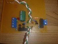
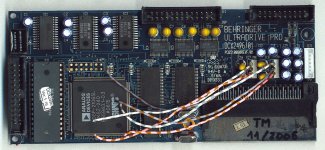
Just a picture about how to do the connections to test the board :
Please someone confirm just just the photo with the real board - again - if it is correct. Thank you!
![IMGDEAD]](https://www.diyaudio.com/forums/<a href=http://www.casimages.com/u/teawke/331241/13283767 target=_blank>[IMGDEAD]http://nsm08.casimages.com/img/2015/05/20//15052001513718964513283767.png[/IMGDEAD])
Please someone confirm just just the photo with the real board - again - if it is correct. Thank you!
An externally hosted image should be here but it was not working when we last tested it.
An externally hosted image should be here but it was not working when we last tested it.
An externally hosted image should be here but it was not working when we last tested it.
![IMGDEAD]](https://www.diyaudio.com/forums/<a href=http://www.casimages.com/u/teawke/331241/13283767 target=_blank>[IMGDEAD]http://nsm08.casimages.com/img/2015/05/20//15052001513718964513283767.png[/IMGDEAD])
Last edited:
Thanks Salas. And again, thanks to marko and PawelPS.
I am very very happy!!
I was afraid of damaging the boards with a bad connection I made.
After following last instructions, the boards are working and measuring well.
One gives 5.2volts, wich is ok for my 5/5.5volts dac.
The other is measuring 3.6 volts after stabilising. It has a green led, jumper and the fast diode - the litle one. I guess I will replace the green led for the red one and get 3,41.
Amanero works with 3,3 but I think 3.41 will be no harm. Can someone confirm?
Both warm up very gently, even after 30 minutes they are almost cold.
Let's ear nowww!!!!!
I soldered my first prototype ( out of five ) on veroboard. It was a nightmare to do but i managed without mistakes and with only three top side vias. I got 6.something volts with off the shelf leds but didn't have more time to try swapping them. The chance of error is incredibly high and I wouldn't recommend anyone to follow my steps. We'll see how the next four shunts turn out but I managed to make a compact and low package.

Since I don't have anything but two digital multi-meters I doubt I can measure the hum let alone jitter. It is an all-digital circuit I'm powering so a possible degradation of performance caused by hum and jitter is almost impossible to asess when the whole PSU will be replaced.
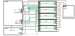
I want to do it right the first time. How about making a star ground point where I'll connect DCin-, 5 times DC- to suppply the shunts and grounds for each of five parts of circuits being powered. So F0 would stay disconnected on the shunt but a thick wire + tin trace will go from DC- to the F0 on the board. S+ and F+ will connect at power input of a circuit and S0 woul be taken from where the wire from the star point connects to the circuit ground.
Does this make any sense?

Since there will be pcb track resistance first connect normally nearest to the consumption target nodes in tight loop areas and if you will get any hum or jitter then you will debug towards alternatives. Like a star for all returns to go, or closing locally on each reg and using shortest possible thick two wire classical connections.
Since I don't have anything but two digital multi-meters I doubt I can measure the hum let alone jitter. It is an all-digital circuit I'm powering so a possible degradation of performance caused by hum and jitter is almost impossible to asess when the whole PSU will be replaced.
I want to do it right the first time. How about making a star ground point where I'll connect DCin-, 5 times DC- to suppply the shunts and grounds for each of five parts of circuits being powered. So F0 would stay disconnected on the shunt but a thick wire + tin trace will go from DC- to the F0 on the board. S+ and F+ will connect at power input of a circuit and S0 woul be taken from where the wire from the star point connects to the circuit ground.
Does this make any sense?
Yes, I had that resistor and changed it for the diode, I did all wrong.
I've a nervous light hand!
I'll use the 62 Ohm resistor as you say, that's precise.
Ok, 1Ohm to cover 500 mA. That's the Dale cpf2, thanks.
You did the example for 3.6V. Its in page 3 too. And it worked exactly to 3.6V. But you need the last example. The 3.3V with the 62 Ohm.
You just did random things believing something was wrong, when there wasn't. Was just running open ended. Then you connected properly to test load. Learning. No burn no harm.
1,0 Ohm R1 will give 610mA current limit so to can serve 500mA demand. There must be 0.61V (about) across R1 and both sinks feel at least warm after 15 minutes.
Last edited:
Better now?
Much better. Will think about it when having a little time soon.
I heard my new dac with the psu, amanero with 5volts from computer, tomorrow I connect the other reflektor to the amanero.
The sound is very good, more open, more space, very good bass, treble is sweet.
The complexity of some notes is evident.
A good psu matters. Tomorrow will comment about the sound with two reflektors.
I'll have a few questions about some modds. Simple questions.
Thank you Salas!
The sound is very good, more open, more space, very good bass, treble is sweet.
The complexity of some notes is evident.
A good psu matters. Tomorrow will comment about the sound with two reflektors.
I'll have a few questions about some modds. Simple questions.
Thank you Salas!
@marko
I don't like the wide loop areas. I would prefer each reg "module" DCIN- to form STAR at RAWOUTDC-. Same for each DCIN+ i.e. individual wires to RAWDC+.
Every FORCE- to its respective PWRGND at the receiving digital boards. FORCE polarity pairs from each reg module to every receiver PCB PWRin points should be twisted. The SENSE pairs also.
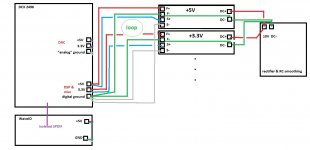
Salas, can you point me where are the loops formed? Don't take my drawing literally. It only shows what is connected where. The star could be at the RAWDCIN-, the S+ and S- in a shielded cable. Individual F+ also.
The problem is all the grounds get eventually connected on the DSP board of the DCX2496.
Here is the schematic of the original PS and the layout of power supply on the DSP board. Also all components of the DCX are on the DSP board.


I made a partial drawing from what you suggest. I cannot separate the ground connections on the DCX, and if I got your suggestion correctly it would form multiple loops.

Thank you very much for your help. I really appreciate it.
The problem is all the grounds get eventually connected on the DSP board of the DCX2496.
Here is the schematic of the original PS and the layout of power supply on the DSP board. Also all components of the DCX are on the DSP board.


I made a partial drawing from what you suggest. I cannot separate the ground connections on the DCX, and if I got your suggestion correctly it would form multiple loops.

Thank you very much for your help. I really appreciate it.
Last edited:
Then I can twist each F-, coming form the shunt to the star at the DSP board , with respective F+ coming form shunt to the power input at the DSP. That way only the incoming DC wires would remain untwisted, with the + away at the power input side, and the - wire could be guided through a small iron pipe if you think it will do harm if left bare.
Hi!
I have one board stabilized in 5.5 volts and other in 3.31Volts. Excellent.
Will it be a big improvement if I feed the dac with two boards with 3,3 replacing the voltage regs or just keep it feeded with 5 volts only -) then it will be splited for the two 3,3 regs.
Can someone you give an opinion?
Also, if I feed the dac with two 3,3 reflektors replacing those regs, do I disconnect the 5 volts board?
Thank you.
axial diodes
I am building my first Reflektor D and I was not sure if I need to jumper the axial diodes if they are not being used, this will be a AC in setup. I see that the manual says not to leave any open in the v ref circuit and I just wanted to be sure about leaving the axial diode locations open Thanks!!Steve
I am building my first Reflektor D and I was not sure if I need to jumper the axial diodes if they are not being used, this will be a AC in setup. I see that the manual says not to leave any open in the v ref circuit and I just wanted to be sure about leaving the axial diode locations open Thanks!!Steve
nope
No, do not do that as it would short the diodes which you are using, leading to smoke, and/or a burnt fuse or transformer.
I am building my first Reflektor D and I was not sure if I need to jumper the axial diodes if they are not being used, this will be a AC in setup. I see that the manual says not to leave any open in the v ref circuit and I just wanted to be sure about leaving the axial diode locations open Thanks!!Steve
No, do not do that as it would short the diodes which you are using, leading to smoke, and/or a burnt fuse or transformer.
- Home
- Amplifiers
- Power Supplies
- Reflektor-D builds
