If, for example, the ESR of C4 were 180 milliohms, then Graeme's new resistor would be (1000 - 180) = 820 milliohms. Figures attached. The book is still in-print and available from Amazon, Barnes & Noble, and others. USD 10.29 at abeBooks dot com (used).
Attachments
Thanks Mark!
But ESR varies with frequency, so at what frequency should one calculate the appropriate resistor value?
Luckily, for X7R capacitors, published data shows enough one should know to have a good image of ESR at various frequencies. For example, for some Kemet X7R multilayer ceramics, I calculated that above 1MHz, ESR should be in the range of 40-100mΩ. Which means that actually a 1R resistor should be installed for peace of mind.
But at lower frequencies, even the electrolytic cap could have enough ESR to damp any resonance. So, at what frequencies do we target to calculate C4's ESR? I assumed that this should be done at high frequencies, where ESR's go low and parasitic inductances shime in, being in the nanoHenry range. Usually it is there where most resonances occur. After all, I know the track dimensions on my pcb, so I can model the whole network accurately enough, inserting track inductance (and resistance).
I wish a Happy New Year to all, by the way!
Trace (and lead) length inductance and low ESR capacitors (eg film dielectric) are the problem parameters that cause the resonance.
It's the low ESR that needs the extra damping of an added resistor.
Usually, an electrolytic and an X7R have sufficient esr to not cause a severe resonance problem.
That's why we avoid using film caps for HF decoupling.
It's the low ESR that needs the extra damping of an added resistor.
Usually, an electrolytic and an X7R have sufficient esr to not cause a severe resonance problem.
That's why we avoid using film caps for HF decoupling.
So far I have designed a layout for a Sulzer regulator (with some small changes regarding protection and changing from tantalum to electrolytic caps). It is an "AC in, DC out" block, meaning that rectification etc is onboard too.
I would like to hear your opinions on my implementation!
General notes:
(1) Protection diodes D5-D6 actually made the circuit as is short circuit proof. I tested that: fuse blows, nothing gets warm. And when I installed a new fuse, output voltage went back to normal. Previously I had murdered a NE5534 since it saw a huge differential voltage between its inputs due to capacitor stored charge, so it seems like these two diodes is all that is needed.
(2) No remote sensing used for my application. Thus, I tried to provide a star method for the + and - of my output voltage.
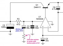
(3) C4 in soldered underneath the IC, to minimise stray inductance.
(4) I tried to keep in/out capacitor paths separate, following your suggestions.
Schematic:

The pcb is double sided, every hole Plated through. Color markings are the following:
Copper top = blue
Copper bottom = green
Silkscreen top = red
Silkscreen bottom = yellow
Pcb layout:

All opinions welcome!
A slightly different propotype I made home "tested normally", in that it performed well as a power supply for 2 guitar pedals (9.2VDC output voltage) - the first one drawing 5mA, the second one 100mA. Sadly I don't have access to a scope to test it yet, but I will soon do - which makes your remarks valuable in terms of saving time.
I would like to hear your opinions on my implementation!
General notes:
(1) Protection diodes D5-D6 actually made the circuit as is short circuit proof. I tested that: fuse blows, nothing gets warm. And when I installed a new fuse, output voltage went back to normal. Previously I had murdered a NE5534 since it saw a huge differential voltage between its inputs due to capacitor stored charge, so it seems like these two diodes is all that is needed.
(2) No remote sensing used for my application. Thus, I tried to provide a star method for the + and - of my output voltage.
(3) C4 in soldered underneath the IC, to minimise stray inductance.
(4) I tried to keep in/out capacitor paths separate, following your suggestions.
Schematic:
The pcb is double sided, every hole Plated through. Color markings are the following:
Copper top = blue
Copper bottom = green
Silkscreen top = red
Silkscreen bottom = yellow
Pcb layout:
All opinions welcome!
A slightly different propotype I made home "tested normally", in that it performed well as a power supply for 2 guitar pedals (9.2VDC output voltage) - the first one drawing 5mA, the second one 100mA. Sadly I don't have access to a scope to test it yet, but I will soon do - which makes your remarks valuable in terms of saving time.
Last edited:
You might want to make the mounting holes and PCB pads for the bridge diodes, large enough to accommodate a 3 amp diode in a DO-201 package (rotated to vertical orientation). As I recall, Rick Miller's TAA article that compared RFI emission from 3 different rectifiers, reported that the lowest RFI was from a 3A diode that happened to be packaged in a DO-201.
In the footprint library that I use, a DO-201 has a 65-mil drill hole and a 95-mil pad, for what it's worth.
(On the other hand, Cx, Rs, and Cs may eliminate the need for a "good" diode
In the footprint library that I use, a DO-201 has a 65-mil drill hole and a 95-mil pad, for what it's worth.
(On the other hand, Cx, Rs, and Cs may eliminate the need for a "good" diode
Last edited:
It might be a good idea to re-state the intended input and output voltage and current ranges, again, for the benefit of "final review" participants who have not read the thread..
At first I was thinking that the fuse rating might be problematical, because it's in the charging pulse path and at turn-on the peak currents will be much higher than normal. But if I recall correctly this is a relatively-low-max-current power supply. And you've specified a slow-blow fuse. So maybe it will be alright.
Edit: Never mind. Sorry. You did state them, at the end of your post (and naturally I stopped reading when I looked at the schematic and the PCB layout and then forgot to go back and finish the text).
Last edited:
Thanks for the answers.
Mark, I will consider your proposal. But then, as you correctly state, I have inserted the snubber network to be able to use cheap universal types. My initial thoughts were on the UF4002 as I show in the schematic, but since they are fast, I don't know whether this should result in more HF ringing to be snubbed, compared to boring 1N4002's. Hopefully, I will test this and find out.
Tom, indeed the power supplies are to be used for 9-16 VDC output and 150mA-200mA DC output current capability. The electrolytic capacitors have a 12.5mm diameter footprint, so this means roughly up to 2200uF for smaller voltages. I will use 1000-1200uF.
Yes the fuse will be closely rated to the VA rating of the winding. This enables me to predict the output short circuit behaviour (since I know that even a T fuse will blow in about 2 seconds if I short the output), with no damage at all. Nothing shall get warm or stressed.
Smaller fuses are obviously an improvement in safety, and in my opinion (given what I have read) it is one of the best reasons to include a soft-start circuit. Soft-start enables you to put smaller fuses. So even though I will use a 100VA toroidal for my build (small), I will include a soft-start circuit with a 200-300ms delay. No fuse should be at actual peril then.
So I assume that you haven't found anything bad to be noted (yet) for my layout!
In case it seems weird, I designed the regs so that they are slim, since I will use 12 of them in one box. 4 pcbs, each one containing 3 regs, each pcb measuring about 10cm long x 8,15cm wide (which gives about 2,72 cm wide per reg).
Mark, I will consider your proposal. But then, as you correctly state, I have inserted the snubber network to be able to use cheap universal types. My initial thoughts were on the UF4002 as I show in the schematic, but since they are fast, I don't know whether this should result in more HF ringing to be snubbed, compared to boring 1N4002's. Hopefully, I will test this and find out.
Tom, indeed the power supplies are to be used for 9-16 VDC output and 150mA-200mA DC output current capability. The electrolytic capacitors have a 12.5mm diameter footprint, so this means roughly up to 2200uF for smaller voltages. I will use 1000-1200uF.
Yes the fuse will be closely rated to the VA rating of the winding. This enables me to predict the output short circuit behaviour (since I know that even a T fuse will blow in about 2 seconds if I short the output), with no damage at all. Nothing shall get warm or stressed.
Smaller fuses are obviously an improvement in safety, and in my opinion (given what I have read) it is one of the best reasons to include a soft-start circuit. Soft-start enables you to put smaller fuses. So even though I will use a 100VA toroidal for my build (small), I will include a soft-start circuit with a 200-300ms delay. No fuse should be at actual peril then.
So I assume that you haven't found anything bad to be noted (yet) for my layout!
In case it seems weird, I designed the regs so that they are slim, since I will use 12 of them in one box. 4 pcbs, each one containing 3 regs, each pcb measuring about 10cm long x 8,15cm wide (which gives about 2,72 cm wide per reg
).
Last edited:
You could go even further and layout the board to accept DO-41 and/or DO-204 and/or TO-220. All of the diodes whose datasheet specifications show extremely soft recovery (S = Tb/Ta), are in TO-220. Think of it as flexibility for future experimentation & enhancement.
Attachments
Thanks Mark.
Regarding your previous remark about adding a damping resistor when using two caps in parallel, I ran some simulations.
First, no added resistor, but every pcb track was given some inductance and series resistance (using some online calculators), and the caps where simulated roughly according to some datasheets.
The circuit:

The first AC analysis:

Then, I made R1 = 1R, so that two cascaded RC filters are used. I did not alter series inductance, but when I did later on, I saw that for HF, the attenuation was better, as one could imagine. So the following picture is possibly worse than reality:

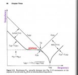
Which indicated that up to 100kHz performance is not compromised. Why would I note this? Since the introduction of the 1R in series with the first cap would create a plateu (as Graeme suggested), which would mean slightly worse attenuation at lower frequencies.
And since the opamp draws low current, I would expect an additional series resistor to have negligible effects on performance.
Just an opinion on that damping method, actually, that could yield better results.
Regarding your previous remark about adding a damping resistor when using two caps in parallel, I ran some simulations.
First, no added resistor, but every pcb track was given some inductance and series resistance (using some online calculators), and the caps where simulated roughly according to some datasheets.
The circuit:
The first AC analysis:
Then, I made R1 = 1R, so that two cascaded RC filters are used. I did not alter series inductance, but when I did later on, I saw that for HF, the attenuation was better, as one could imagine. So the following picture is possibly worse than reality:
Which indicated that up to 100kHz performance is not compromised. Why would I note this? Since the introduction of the 1R in series with the first cap would create a plateu (as Graeme suggested), which would mean slightly worse attenuation at lower frequencies.
And since the opamp draws low current, I would expect an additional series resistor to have negligible effects on performance.
Just an opinion on that damping method, actually, that could yield better results.
Last edited:
Since the introduction of the 1R in series with the first cap would create a plateu (as Graeme suggested), which would mean slightly worse attenuation at lower frequencies.
Beyond that, you're just attenuating lower and lower frequencies, which the opamp's PSRR would have attenuated anyway.
Yes, Graeme explicitly trades worse performance at LF for better performance at HF. He trusts that PSRR will make up the difference, since PSRR is proportional to open loop gain, and open loop gain rises as frequency falls.
This is why mfr datasheets of >175 MHz current feedback opamps call for 1-10 uF Solid Tantalum electrolytic bypass capacitors, in parallel with 0.1uF NPO/C0G ceramic. It just so happens that a Solid Tantalum's ESR is ~exactly the Graeme-approved series resistance. So you don't need to plop down an external resistor on the PCB, in this super-tight-layout region. You get it "for free" when you install the Solid Tantalum.
Is 1.00 ohms the optimal value of additional series resistance? If one ohm is good, perhaps two ohms are better, and four ohms are even more delightful? Sounds like a job for LTSPICE's directive called .STEP PARAM .
You may even be willing to take the total series resistance from Q1_collector to Opamp_Vpos, and partition it differently. Instead of (47 ohms followed by 4 ohms), perhaps you are willing to try (25 ohms followed by 25 ohms), and/or other partitionings. Maybe Mike Sulzer just wasn't aggressive enough?? Yet another .STEP PARAM to explore.
You may even be willing to take the total series resistance from Q1_collector to Opamp_Vpos, and partition it differently. Instead of (47 ohms followed by 4 ohms), perhaps you are willing to try (25 ohms followed by 25 ohms), and/or other partitionings. Maybe Mike Sulzer just wasn't aggressive enough?? Yet another .STEP PARAM to explore.
So I will try to check my propotype's marginal stability using the switching MOSFET-load application.
A couple of questions on that:
(1) I realise that low nC and big current capability will give me fast rise times. And for the 555 timer, Mark calculated that with a low Q_tot MOSFET, the rise time should be about 33ns, if I remember correctly. That suggests that rise time will depend only on these two parameters - I mean that I can take for granted that 555 is able to switch even in a couple of nanoseconds, should Q_tot be ridiculously low. Correct?
(2) The way I undestand your remarks, I assume that since rise time is directly related to bandwidth, then a given rise time will aid in judging stability of the regulator within that corresponding bandwidth. For example, for 33ns, this means that BW is roughly 10MHz: say I test the regulator with such a load, and find no overshoots, oscillations etc. That means that the regulator behaviour will be stable up to 10MHz. Right?
I also assume that after evaluating the open loop response of the regulator block, then the test should be set to confirm that the system is stable up to the unity-gain frequency. So if unity gain for the open loop is achieved at 100MHz for example, then one should test the regulator for up to 100MHz, or with a 3.4ns rise time pulse. Does that make any sense?
Last edited:
Is 1.00 ohms the optimal value of additional series resistance? If one ohm is good, perhaps two ohms are better, and four ohms are even more delightful? Sounds like a job for LTSPICE's directive called .STEP PARAM .
You may even be willing to take the total series resistance from Q1_collector to Opamp_Vpos, and partition it differently. Instead of (47 ohms followed by 4 ohms), perhaps you are willing to try (25 ohms followed by 25 ohms), and/or other partitionings. Maybe Mike Sulzer just wasn't aggressive enough?? Yet another .STEP PARAM to explore.
Mark, I would like to ask you a question on this one. I realise that inserting a series resistor before the 100nF cap will mean that the voltage will modulate according to the current drawn by the opamp. Which will depend on the load. I assume that even for fast transients this is what will happen, since I doubt that the 100nF decoupling cap can provide enough charge before its voltage falls. Is this wrong?
Of course, this voltage modulation will be very low for my application, and the current demands of the IC are tiny. But could this make manners worse? This is a general question I have on power supply filtering anyway. What I have understood so far, is that a large C in an RC combo can provide enough charge for large currents before its voltage falls, so that voltage does not sag due to the presence of the series resistor. But do you still kep that effect, if you insert an RC combination with a very low C value?
Draw current from a capacitor and it's voltage will fall. It cannot be any other way.
The point is, that the capacitor at the load can provide current much faster than can be sent along inductive supply lines.
The very fast current demand is met by the HF decoupling.
This decoupling is recharged by the MF decoupling.
The MF decoupling also supplies slower changes in current demand, where some inductance in the supply lines does not give large Vdrops.
The main smoothing capacitance then recharges the MF decoupling. It does this comparatively slowly due to the very high impedances in the supply lines from the PSU to the circuit demanding changing current.
It's the CHANGING Current Demand that MUST be met as well as possible for good VHF performance.
If the current never changed, then you could place your PSU a mile away and not bother using any decoupling at the load. The voltage at the load would not waver and the DC performance of the load would not waver, even if the PSU were a hundred miles away.
Draw current from a capacitor and it's voltage will fall. It cannot be any other way.
The point is, that the capacitor at the load can provide current much faster than can be sent along inductive supply lines.
The very fast current demand is met by the HF decoupling.
This decoupling is recharged by the MF decoupling.
The MF decoupling also supplies slower changes in current demand, where some inductance in the supply lines does not give large Vdrops.
The main smoothing capacitance then recharges the MF decoupling. It does this comparatively slowly due to the very high impedances in the supply lines from the PSU to the circuit demanding changing current.
It's the CHANGING Current Demand that MUST be met as well as possible for good VHF performance.
If the current never changed, then you could place your PSU a mile away and not bother using any decoupling at the load. The voltage at the load would not waver and the DC performance of the load would not waver, even if the PSU were a hundred miles away.
Totally correct. Then, how bad would it be to insert a 10R resistor after the MF decoupling and the HF decoupling? Since based on the above, slower changes in current demand will take that route. Would we care if this resistor modulates the voltage seen at the IC pins by 40-50mV?
40 to 50mV sounds like far too much.
+-1mV would be a lot.
So you would advise against using an RCRC filter, consisting of 47R-220uF-10R-0.1uF, that filters a NE5534's pins, right?
Is 1.00 ohms the optimal value of additional series resistance? If one ohm is good, perhaps two ohms are better, and four ohms are even more delightful?
Don't forget that the practise of a resistor in series with an opamp supply was meant to avoid that the opamp-created ripple would propagate back to other opamps or circuit parts on the same supply. The resistor, with the supply capacitor (NOT the cap on the opamp supply) was attenuating the created ripple that would end up on the supply line.
Designers realised that that did increase supply impedance for the opamp and to battle that they put a capacitor on the opamp supply pin.
So when you have a very good supply, like a super reg
, the R-C thing makes matters worse and sould not be used.Jan
.. like a super reg
Jan
True, but here I am building a Sulzer regulator! As you might remember, this design uses a filtered version of the collector voltage into the opamp - Mike Sulzer used 47R-47uF+100nF.
I am also planning to use a 0.1uF decoupling right on the IC pins, and my RC stage should be 47R-220uF. The discussion started out as to whether a resistor should be used to damp possible resonances caused by paralleling the caps. I initially suggested using an RCRC configuration not to spoil the 220uF's rejection, the second R being 1R, and Mark suggested that second R could be made bigger. According to my reasoning and AndrewT's posts, it seems like such a second resistor should degrade performance. What is your take on that?
- Status
- This old topic is closed. If you want to reopen this topic, contact a moderator using the "Report Post" button.
- Home
- Amplifiers
- Power Supplies
- Accurate voltage regulation