a low esr capacitor fed by inductive supply rails, can oscillate if a fast starting, or fast stopping, transient disturbs the current flow.
The solution is to not use a low esr capacitor.
You can select capacitors that inherently have higher esr inside, or add a physical resistor to the capacitor.
That is not the same as adding a resistor into the supply rail.
The solution is to not use a low esr capacitor.
You can select capacitors that inherently have higher esr inside, or add a physical resistor to the capacitor.
That is not the same as adding a resistor into the supply rail.
True, but here I am building a Sulzer regulator! As you might remember, this design uses a filtered version of the collector voltage into the opamp - Mike Sulzer used 47R-47uF+100nF.
I am also planning to use a 0.1uF decoupling right on the IC pins, and my RC stage should be 47R-220uF. The discussion started out as to whether a resistor should be used to damp possible resonances caused by paralleling the caps. I initially suggested using an RCRC configuration not to spoil the 220uF's rejection, the second R being 1R, and Mark suggested that second R could be made bigger. According to my reasoning and AndrewT's posts, it seems like such a second resistor should degrade performance. What is your take on that?
OK so its the opamp in the regulator. The goal is to have a supply that is very much like a (almost) perfect DC, so I don't see any advantage of supplying the opamp through a resistor, with or without cap.
I understand the concern about oscillation, but that should not be a problem unless you have very high Q caps at the output with no ESR.
I wouldn't do it.
Jan
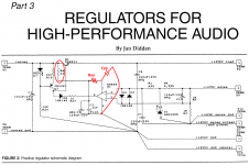
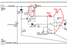
Jan, he is talking about your resistor "R6" from your 1995 article, schematic below.
He wonders whether it is a good idea to split R6 into two series components, R6 and Rxx. Then whether or not to add a new capacitor Cyy. And if the answer is yes, if doing this is an improvement, he wonders what are the optimum values of (a) the sum (R6 + Rxx); (b) the ratio (R6 / Rxx).
He wonders whether it is a good idea to split R6 into two series components, R6 and Rxx. Then whether or not to add a new capacitor Cyy. And if the answer is yes, if doing this is an improvement, he wonders what are the optimum values of (a) the sum (R6 + Rxx); (b) the ratio (R6 / Rxx).
Attachments
Jan, he is talking about your resistor "R6" from your 1995 article, schematic below.
He wonders whether it is a good idea to split R6 into two series components, R6 and Rxx. Then whether or not to add a new capacitor Cyy. And if the answer is yes, if doing this is an improvement, he wonders what are the optimum values of (a) the sum (R6 + Rxx); (b) the ratio (R6 / Rxx).
Ahhh! I see.
Well, in the new regulator, updated per Walts' 2000 article, that R6 is gone, together with the cap. The opamp is now supplied direcly from Vout. See the article.
Problem solved.
Sometimes, very sometimes, you can eat your cake and have it too
Jan
If I were the designer, I would work hard to make the simulations as thorough and error-free as possible. Then I would find out which topology is optimum in simulation, and what element values are optimum. What works best in simulation, is what I would use.
I would treat the opinions of other people, as ideas-to-be-simulated.
I would treat the opinions of other people, as ideas-to-be-simulated.
If I were the designer, I would work hard to make the simulations as thorough and error-free as possible. Then I would find out which topology is optimum in simulation, and what element values are optimum. What works best in simulation, is what I would use.
I would treat the opinions of other people, as ideas-to-be-simulated.
Yes, I simulate a lot. But in this case, apart from deriving a frequency response plot and find optimum values, I don't know how to implement a sim to see whether such a filter helps.
The whole point is about whether this second resistor will modulate the voltage at the IC, which is a bad thing since we want DC. And it seems like it will - the 0.1uF is tiny to be able to supply lots of current without drops of voltage. Do you agree with this?
I haven't run the simulations; I don't have an opinion.
You could lay out the PCB including R6 and Rxx and C2 and C5 and Cyy. Then you could experiment: what happens if Rxx is a zero-ohm jumper? What happens if R6 = Rxx = 11 ohms? etc. You could even lay out the PCB so that R6 and Rxx are each laid out as a fixed resistor in parallel with a multi-turn trimmer potentiometer. Now you can populate R6 / Rxx either with a fixed resistor, or a trimmer, or a jumper, for additional fine-grained experimentation.
This is deferred decision making, sometimes called "the mañana principle" ("mañana" is the Spanish word for "tomorrow"): don't do it today if you can do it tomorrow. In your case it transfers the task of data-gathering and data-evaluation, from today (design work) to tomorrow (measurement and checkout work). It also means you aren't relying upon simulation; instead you rely upon physical measurement. Some people are not comfortable relying upon SPICE.
Yes but I am talking Sulzer regulator in this thread!
EDIT: Mark, do you have an answer to my wonders? Actually you got me into thinking about them.
Is there a reason to use the Sulzer that I've been missing? I mean, just move one wire and you're done...
Jan
Is there a reason to use the Sulzer that I've been missing? I mean, just move one wire and you're done...
Jan
I want to build 12 good quality regs, better than LM317, but I don't need super regulator performance. Mainly to gain knowledge.
I have space limitations that I have set and want to follow, so a Sulzer regulator was the easiest tiny-fit I could implement. I would really like to power the opamp from the output (as you say, move one wire) but I am asking you (due to your expertise in this): Do I need to fit a start-up zener too?
The way I see it, I could just power the existing Sulzer's IC reg from the output, so I would save some filtering parts. But do I need to insert that zener too? I could go up to that and remain within my room specs, can't afford the space it takes for an additional current source etc.
Mark, sadly I don't think it is possible to test whether it would make a difference. You want me to test whether a resistor in series with an opamp supply (that will modulate its DC voltage according to current demand, which in theory isn't good) that already has good PSRR will make an audible or measurable difference. I have neither the equipment to do that, nor the knowledge. So I am just wondering what is better in theory - design something so that is has -60dB rejection at MHz but a better DC supply, or ensuring -80dB rejection but DC modulations?
Dont have my stuff with me, but did the Sulzer have a diode in series with the opamp output? If so replace with a zener of half Vout.
Jan
No it didn't. So for a 9V supply I should get a (roughly) 4.5V zener and bypass it with a cap to lower noise? I don't quite remember the use of the cap in the super regulator actually.
If it's all it gets, I will try it!
Jan, your "Sulzer regulator" design did have a series diode, it was called D8.Dont have my stuff with me, but did the Sulzer have a diode in series with the opamp output? If so replace with a zener of half Vout.
Jan
Attachments
Yes, replace it with a half Vout zener tot place the opamp output in the middle of its range. Then feed the opamp from Vout. Whats your nominal Vout?
Jan
9V and 16V.
I now see that to install a zener diode, you must also use the constant current source to bias the zener and achieve start-up. So this means that if I am to power it from Vout, I am totally abandoning Sulzer schematic and go to a super regulator.
I thought a cheap alternative would be to insert a 1k resistor between collector and emitter of the pass transistor to ensure a DC current flows to bias the zener. But I think this would provide a path for raw DC ripple (that comes beforehand) which isn't good. Any thoughts on that?
I thought a cheap alternative would be to insert a 1k resistor between collector and emitter of the pass transistor to ensure a DC current flows to bias the zener. But I think this would provide a path for raw DC ripple (that comes beforehand) which isn't good. Any thoughts on that?
Ok. Now it's time for a delicate choice in layout for my Sulzer regulator.
I will present you two different versions of the layout I have designed. The only difference is the connection of the ground point for the opamp. I would like to hear your opinions on my final choice - I have one preference and I will explain it. The schematic used (with protection diodes omitted for clarity):

My references for the output voltage are directly on the pins of C7. This means that my common point for the circuit is taken as the negative pin of C7. Filtering capacitor C3 will be placed close to NE5534 for obvious decoupling reasons. So what remains to be done is to connect NE5534's pin 4 to a suitable reference.
I have found there are two ways, and I name them ground 1 and ground 2. From what I have understood, ground 2 version was used in 1995 Jung regulators, when filtering into the IC was still used. The different implementations follow.
Ground 1:

Ground 2:

My preference is ground 1. My choice depends on the DC stability of the common reference that is presented to the opamp, and that largely depends on the trace resistance that connects pin 4 to output ground + the current that flows through that trace:
(1) For ground 1 option, that trace is shorter and carries only the charging current of C3. This corresponds to roughly 10mΩ of trace resistance and a "ripple" current of no more than 10-15mA. So voltage modulation should be subtle.
(2) For ground 2 option though, the trace resistance is higher since the route is larger, and the voltage seen at pin 4 is modulated by the following currents: the current that the IC demands, the charging current of C3 and, most importantly, the load current. Given the fact that load current could be 60-200 times bigger than ground 1 option (since D44H11 specifies for a minimum of 60 hfe) I consider ground 2 a poor choice.
What are your thoughts on my take?
I will present you two different versions of the layout I have designed. The only difference is the connection of the ground point for the opamp. I would like to hear your opinions on my final choice - I have one preference and I will explain it. The schematic used (with protection diodes omitted for clarity):
My references for the output voltage are directly on the pins of C7. This means that my common point for the circuit is taken as the negative pin of C7. Filtering capacitor C3 will be placed close to NE5534 for obvious decoupling reasons. So what remains to be done is to connect NE5534's pin 4 to a suitable reference.
I have found there are two ways, and I name them ground 1 and ground 2. From what I have understood, ground 2 version was used in 1995 Jung regulators, when filtering into the IC was still used. The different implementations follow.
Ground 1:
Ground 2:
My preference is ground 1. My choice depends on the DC stability of the common reference that is presented to the opamp, and that largely depends on the trace resistance that connects pin 4 to output ground + the current that flows through that trace:
(1) For ground 1 option, that trace is shorter and carries only the charging current of C3. This corresponds to roughly 10mΩ of trace resistance and a "ripple" current of no more than 10-15mA. So voltage modulation should be subtle.
(2) For ground 2 option though, the trace resistance is higher since the route is larger, and the voltage seen at pin 4 is modulated by the following currents: the current that the IC demands, the charging current of C3 and, most importantly, the load current. Given the fact that load current could be 60-200 times bigger than ground 1 option (since D44H11 specifies for a minimum of 60 hfe) I consider ground 2 a poor choice.
What are your thoughts on my take?
Today I performed a crude test on my Sulzer regulator. Here are my findings:
I applied a switching mosfet load, as Mark Johnson had kindly suggested. I used a FQPF13N06L, driven by a signal generator that fed its gate with a 10kHz, 10Vpp pulse. The regulator's output voltage was about 9Vdc. I implemented the two following scenarios:
(1) Placed the load as close as possible to the reg.
(2) Connected the load to the reg using a 1m twisted pair cable.
On both occasions, I observed some quickly dying oscillations around the point of current load change, as expected. On scenario (1), it had a peak of about 1V, whereas on scenario (2), it had a peak of about 1,5V. In both cases, the period of oscillations was in the order of 20-50 ns, if I recall correctly. Sadly I forgot to take pictures - will do next time.
The oscillations died after about 100ns. But here is an important note: I never used decoupling caps close to the load, on purpose.
But when I did, the oscillations completely dissappeared. Even when the decoupling cap was a 220n film, even when it was a Silmic II 220uF 16V, even when it was a crappy cheap chinese 1uF electrolytic.
The behaviour never changed, even when I used compensating caps ranging from 1pF to 560pF, even when I desoldered the 100n X7R that rests across the NE5534 pins.
So what I seem to understand, is that it doesn't seem to be a stability issue of the reg, but normal spikes caused by the parasitic inductance of the connections, since heavy current changes occured. This is actually my main argument, and I would like your opinion on that, since I have limited experience on stability issues.
Important details: I used a Hewlett Packard 250MHz Digitizing Oscilloscope, and the measured current pulse across the load resistors had a rise time of about 20ns (the machine calculated its average value to be 19,75 ns).
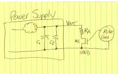
I hope you remembered to include resistor Rx in your testing circuit. The purpose of pulse testing is to create an ideal square wave current waveform. Resistor Rx determines the magnitude of this current: I = Vout/Rx. If Rx=zero then the current becomes extremely large and poorly controlled.
The goal is to find out whether the power supply's negative feedback control loop becomes unstable when loaded by an ideal square wave current waveform. Adding capacitors just for the test, distorts the current waveform, which reduces confidence in the results.
The goal is to find out whether the power supply's negative feedback control loop becomes unstable when loaded by an ideal square wave current waveform. Adding capacitors just for the test, distorts the current waveform, which reduces confidence in the results.
Attachments
I hope you remembered to include resistor Rx in your testing circuit. The purpose of pulse testing is to create an ideal square wave current waveform. Resistor Rx determines the magnitude of this current: I = Vout/Rx. If Rx=zero then the current becomes extremely large and poorly controlled.
The goal is to find out whether the power supply's negative feedback control loop becomes unstable when loaded by an ideal square wave current waveform. Adding capacitors just for the test, distorts the current waveform, which reduces confidence in the results.
Yes, I used Rx=45 ohms. And a 1k ohm resistor parallel to M1 (across D-S).
Does the behaviour of the circuit seem rational?
- Status
- This old topic is closed. If you want to reopen this topic, contact a moderator using the "Report Post" button.
- Home
- Amplifiers
- Power Supplies
- Accurate voltage regulation