Many thanks for the response. Yes, maybe I will just sweep frequencies from low to high, within the generator limits.
Any recommendations for this mosfet, by the way? Sadly, I am not familiar with real world parts yet.
You alluded to it in a later post: I meant to say that you could/should (slowly) sweep the rise and fall times, not the repetition rate (frequency). Pulse generators usually have knobs for the rise and fall times. Surplus pulse gens are often very cheap.
You would probably want to keep the frequency (i.e. the square or pulse wave repetition rate) relatively slow, so you would have a long-enough interval to see if any ringing or oscillation developed, after each fast edge hit the system.
High frequency is inherent in fast-rising and fast-falling edges and their corners. [ fmax = 1 / ( π trise) ]
One more point: In case you do see some ringing, remember to compare the pulse-edge response of your circuit to the response when the pulse gen is connected only to a non-inductive resistor that has about the same impedance as your circuit presents to the pulse gen, to rule out the measurement setup. Remember to re-adjust the probe compensation, too.
Last edited:
The original Sulzer regulator uses a 47uF tantalum plus one 470nF film capacitor at the output. And is stable up to 100mA, according to the original articles.
He also suggests that a 330uF low esr electrolytic capacitor could be alternatively used, instead of a 47uF tantalum.
For the high-current version of the regulator (above at least 1A), he suggested that the output capacitor was composed out of several parallel 330uF electrolytics, or something close to it (470uF etc).
From all this, I understand that for higher currents, more output capacitance is needed for stability. From the articles, I understand that more capacitance can't harm.
So, I need a maximum of 200mA for my versions. Then, is it possible that I can ensure stability up to 200mA just by adding more capacitance? This is a theoretical approach, that could save me some time planning tests and layouts.
I also understood that stability at high currents is a matter of having low impedance at the output, achieved by many paralleled capacitors. Is this true? Is this all that it takes to ensure that stability is not at peril?
After all, I believe that if just low impedance is needed, then maybe a 330uF today's electolytic cap could outscore a 47uF tantalum of the 80's, when the article was originally written. In that manner, maybe a good quality, low esr cap of above 100uF would suffice for the application I need. Does this make any sense?
He also suggests that a 330uF low esr electrolytic capacitor could be alternatively used, instead of a 47uF tantalum.
For the high-current version of the regulator (above at least 1A), he suggested that the output capacitor was composed out of several parallel 330uF electrolytics, or something close to it (470uF etc).
From all this, I understand that for higher currents, more output capacitance is needed for stability. From the articles, I understand that more capacitance can't harm.
So, I need a maximum of 200mA for my versions. Then, is it possible that I can ensure stability up to 200mA just by adding more capacitance? This is a theoretical approach, that could save me some time planning tests and layouts.
I also understood that stability at high currents is a matter of having low impedance at the output, achieved by many paralleled capacitors. Is this true? Is this all that it takes to ensure that stability is not at peril?
After all, I believe that if just low impedance is needed, then maybe a 330uF today's electolytic cap could outscore a 47uF tantalum of the 80's, when the article was originally written. In that manner, maybe a good quality, low esr cap of above 100uF would suffice for the application I need.
Does this make any sense?I recommend you study this in the frequency domain (spice .AC analysis). You may find that the regulator's open loop output resistance forms a pole with the capacitance of the tantalum (or polymer, or aluminum) electrolytic capacitor on the output, and the capacitor ESR creates a higher frequency zero. You may find this pole-zero pair increases output impedance at mid-frequencies since the 2nd pole reduces open loop gain, and thus reduces the amount of NFB available. You might even find that some combinations of (Cout, ESRout) have dangerously low phase margin. Perhaps even outright instability.
Be sure to test this at three different DC output currents: Iout_min, Iout_max, and inbetween; since open loop output resistance varies with output current.
Be sure to test this at three different DC output currents: Iout_min, Iout_max, and inbetween; since open loop output resistance varies with output current.
To do this, I assume I need particular values of ESR and ESL. Thus, I imagine you suggest I use a variety of possible values, using any information I might get hold of.
When you say open loop, you mean no load and capacitor attached? Do these two elements form the closed loop?
When you say open loop, you mean no load and capacitor attached? Do these two elements form the closed loop?
Mark,
I did a small search on this, and I read that there are generally three methods for checking stability (in simulation or in reality, I suppose):
(1) step input response: I assume you look at the output of the regulator (under load? I see no reason to exclude the load) when the input is a fast rise time step waveform
(2) inserting an AC source in the reference divider leg that goes to the + input of the opamp, and performing an ac analysis while looking at the ratio of the voltages across it (more here: http://www.diyaudio.com/forums/solid-state/226848-how-model-stability-analysis-linear-regulator-such.html)
(3) performing fast load current changes in the load with the aid of a MOSFET acting as a switched load, which is something you have already suggested I do in reality
Which of the above three is your suggestion regarding AC spice simulation? I couldn't decide based on your post #185.
Pardon me for jumping in, but keep in mind that with many regulators, stability requires the output cap's esr to be above some value.
Also, of the three methods you mentioned, the "best" one is breaking the loop, because you can read the actual phase and gain margins from the plots.
There are .asc files that have been posted here that have the method. I even put some here, years ago. Maybe I can find them. I will try to provide a link, if Mark doesn't.
Do a search for Tian Probes.
Last edited:
I agree with Bob Cordell (p. 416) and Tom Gootee. I prefer to simulate open loop gain (and phase) by breaking the feedback loop, injecting an AC signal at the input side of the break, and observing (plotting) the results at the output side of the break, after it has gone all the way around the feedback loop. I prefer to do this the old fashioned way, without Tian Probes. As Tom Gootee said back in Jan 2008 (link)
Another way to skin the cat, which I happen to like, is to break the loop at all frequencies of interest, but keep the loop closed at DC. In other words, to insert a low pass filter with a VERY low cutoff frequency; a pole at or below 1E-7 Hertz. Phillip Allen of Georgia Tech illustrates this in slide 3 of the attached lecture notes; he uses an RC lowpass filter to break the feedback loop at all frequencies of interest {the right hand half of the Bode plot}, and he makes its cutoff frequency very low by setting the RC timeconstant as large as possible. Bob Cordell goes one step further and breaks the loop using an LC filter (whose slope is twice as steep as an RC filter). Bob advises setting L = 1E+12 Henries (!!).
... to find the phase margin, to judge the stability of a feedback system, you have to do it with the OPEN-loop gain and phase.
... with "the simple method", you can insert an AC source just before a high-impedance input, such as the summing node for your feedback, with the source's + output toward the high-impedance node. If the AC source's + side is labeled In and the - side is labeled Out, then you can plot V(Out)/V(In). If the high-impedance node is really high-impedance, such as an opamp input, then the simple AC source method should be accurate-enough up to tens of MHz.
Another way to skin the cat, which I happen to like, is to break the loop at all frequencies of interest, but keep the loop closed at DC. In other words, to insert a low pass filter with a VERY low cutoff frequency; a pole at or below 1E-7 Hertz. Phillip Allen of Georgia Tech illustrates this in slide 3 of the attached lecture notes; he uses an RC lowpass filter to break the feedback loop at all frequencies of interest {the right hand half of the Bode plot}, and he makes its cutoff frequency very low by setting the RC timeconstant as large as possible. Bob Cordell goes one step further and breaks the loop using an LC filter (whose slope is twice as steep as an RC filter). Bob advises setting L = 1E+12 Henries (!!).
Attachments
So I started my try to perform this AC analysis for stability.
(1) I assume that the load has to be a constant current source, not a single resistor.
(2) Is it mandatory to include esr et for all caps of the regulator, or just for the output one?
EDIT: Also, what are the results of phase I have to expect that ensure stability?
(1) I assume that the load has to be a constant current source, not a single resistor.
(2) Is it mandatory to include esr et for all caps of the regulator, or just for the output one?
EDIT: Also, what are the results of phase I have to expect that ensure stability?
Last edited:
So, some first results. But I don't know if they are of any use at all.
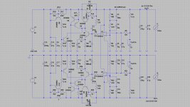
Schematic in Pspice:

I didn't know what to do with the compensation pins of the NE5534 (I leave them unconnected in reality), so I added a 0.1pF parasitic capacitance between them. I don't know if this value is reasonable at all.
To begin with, I only used DC voltages for all nodes that are DC at theory - raw DC supply at the collector of Q1, power supply for the opamp and the reference zener (LM329) is replaced by a 6.83V DC source.
I attached no load at the output. Will do it later.
When suggesting a 10m esr for the 47uF output capacitor, results are the following (P() is the phase plot):

For 1R of output cap esr (have read this as specification for Kemet tantalums), results are the following:

Sadly, I can't comment on the results with my experience. Do they seem rational at all?
Schematic in Pspice:
I didn't know what to do with the compensation pins of the NE5534 (I leave them unconnected in reality), so I added a 0.1pF parasitic capacitance between them. I don't know if this value is reasonable at all.
To begin with, I only used DC voltages for all nodes that are DC at theory - raw DC supply at the collector of Q1, power supply for the opamp and the reference zener (LM329) is replaced by a 6.83V DC source.
I attached no load at the output. Will do it later.
When suggesting a 10m esr for the 47uF output capacitor, results are the following (P() is the phase plot):
For 1R of output cap esr (have read this as specification for Kemet tantalums
), results are the following:
Sadly, I can't comment on the results with my experience. Do they seem rational at all?
Today, I did a short-circuit test for my Sulzer circuit.
The output voltage was tested as 9.20V both for no load and 150mA DC load.
Then, I performed an artificial output short circuit. Luckily, nothing smelt, got hot or vapourised before the fuse blew! A 0.63T one.
So, afterwards, I replaced the fuse and powered it up again see whether it could go on. The result was a bit weird: I now got 9.42V DC output no load voltage, which fell to 9.10V for a full, 150mA DC load.
I checked the LM329 during no load, and its voltage was correctly 6.83V, as it was initial. But the voltage seen at the + input of the NE5534 was 6.96V (after the RC filter)! The voltage at the inverting input was 6.96V too, indicating that the opamp did its job.
But at full load, voltage at + input went down to 6.78V.
From this, I seem to understand that NE5534 got damaged, and was sourcing and drawing current at its + input during no load and full load respectively. So I went on and replaced it with an LF351N. The result was stable 9.20V DC output for both no load and full load.
So it seems the opamp gets damaged! What is a way of preventing this from happening? Maybe a series resistor with the opamp's output?
What could be the cause of this damage?
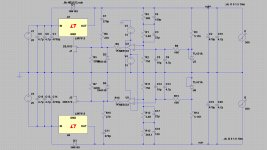
EDIT: I attach the schematic of the tested circuit for convenience.

The output voltage was tested as 9.20V both for no load and 150mA DC load.
Then, I performed an artificial output short circuit. Luckily, nothing smelt, got hot or vapourised before the fuse blew! A 0.63T one.
So, afterwards, I replaced the fuse and powered it up again see whether it could go on. The result was a bit weird: I now got 9.42V DC output no load voltage, which fell to 9.10V for a full, 150mA DC load.
I checked the LM329 during no load, and its voltage was correctly 6.83V, as it was initial. But the voltage seen at the + input of the NE5534 was 6.96V (after the RC filter)! The voltage at the inverting input was 6.96V too, indicating that the opamp did its job.
But at full load, voltage at + input went down to 6.78V.
From this, I seem to understand that NE5534 got damaged, and was sourcing and drawing current at its + input during no load and full load respectively. So I went on and replaced it with an LF351N. The result was stable 9.20V DC output for both no load and full load.
So it seems the opamp gets damaged! What is a way of preventing this from happening? Maybe a series resistor with the opamp's output?
What could be the cause of this damage?
EDIT: I attach the schematic of the tested circuit for convenience.
Last edited:
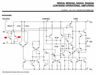
When the output got shorted to ground, capacitor C6 immediately yanked the opamp's VIN- pin to ground. Meanwhile, capacitor C5 kept the opamp's VIN+ pin at ~6.8 volts. The right hand red diode in the attached schematic, thus had 6.8 volts of forward bias. Since it's an exponential device, it conducted Infinity amperes with VBE = +6.8V, and it blew up.
What's a fix? You could consider installing back-to-back diodes across the 5534's input pins, IF you pick diodes whose forward voltage is significantly smaller than the red diodes inside the 5534. What rhymes with Bottkie? (these diodes) might be a good choice: 0.53V forward voltage, 10uA leakage, 16pF capacitance.
Or you could switch to a JFET-input opamp; they can tolerate enormous delta-V across their VIN+ and VIN- terminals. Burr Brown / TI has lots of them in their OPA series. Analog Devices has quite a few as well.
Attachments
Last edited:
Thank you both for the excellent responses.
I must admit I had no time to troubleshoot the situation, but even if I realised the differential voltage existed I would not remember that this is problematic. Will keep that in mind for future builds.
Mark, thanks for the recommendations. But I would rather stick to through hole parts for the time being. So, why not use generic 1N4148 diodes? I see they are used in the Super Regulator too.
The specify 4pF capacitance, they conduct quite early (maximum drop is 1V, not bad, and will be at higher currents) and as for leakage, I read that maximum is 50uA at 150C ambient! Waaaay higher than it will be exposed to. They seem to be well under the 10uA for reverse voltages up to 20V - and, normally, they should see zero difference, so lower leakage too.
I will first try the diodes + NE5534 solution, since the circuit is known to be stable for this particular uncompensated opamp. If it doesn't survive the short output test, given good possible diodes are used, I might resort to opamp rolling.
I have found some decent diodes to use, in my opinion. 1N4151, SD101C or BAT81S seem to be cheap and good enough for the purpose.
So I was thinking that maybe only one diode in needed for the opamp to survive the output short-circuit test, connecting its anode to the + input and the cathode to the - input. Since as you mentioned, a large differential voltage of more than 7V should appear at the input terminals, but should have its positive end on the + input. Not trying to save costs here actually, rather than space - I have already made a tight layout, and I am a bit lazy of rearranging everything all together.
Considering that the original circuit used no diodes, it should be an improvement anyway. I will try and see how it goes.
So I was thinking that maybe only one diode in needed for the opamp to survive the output short-circuit test, connecting its anode to the + input and the cathode to the - input. Since as you mentioned, a large differential voltage of more than 7V should appear at the input terminals, but should have its positive end on the + input. Not trying to save costs here actually, rather than space - I have already made a tight layout, and I am a bit lazy of rearranging everything all together.
Considering that the original circuit used no diodes, it should be an improvement anyway.
I will try and see how it goes.
Last edited:
Referring to post 192, does C3 value affect at all stability of the regulator?
If making it bigger doesn't harm, then it would be beneficial to make it bigger, to provide more filtering of the incoming voltage, improving the opamp's PSRR at high frequencies. Maybe this could also ensure that more voltage headroom is present, since R3 could perhaps get smaller too.
Another concern could be that the value of C3 could be critical, as not to form a tuned LC filter with C4. But in my implementation, C4 is attached directly to the pins of the opamp, rather than in parallel with C3.
Opinions?
Jerald Graeme's book recommends C3 > (50/(pi*GBW)) where GBW is the Gain Bandwidth Product of the opamp: 10MHz for the NE5534. Plugging in the numbers, C3 > 1.6uF. Beyond that, you're just attenuating lower and lower frequencies, which the opamp's PSRR would have attenuated anyway.
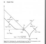
Graeme suggests you install a series resistor between C3's bottom plate and ground. He recommends this series resistor's value should be (1.0 ohms, minus the ESR of C4). Graeme emphasizes that this 3 element network (C3, C4, series resistor) gives a broad plateau in the graph of impedance vs. frequency, and eliminates unwanted resonant interactions between C3 and C4. A figure from that book is attached below.
Graeme suggests you install a series resistor between C3's bottom plate and ground. He recommends this series resistor's value should be (1.0 ohms, minus the ESR of C4). Graeme emphasizes that this 3 element network (C3, C4, series resistor) gives a broad plateau in the graph of impedance vs. frequency, and eliminates unwanted resonant interactions between C3 and C4. A figure from that book is attached below.
Attachments
Thanks Mark!
Sadly, I did not quite understood the "bottom plate to ground" remark. Do you mean in series with C3, and this series combination in parallel with C4, or creating a cascaded RC filter following the C3-R3 one?
If the resistor is placed in series with C3, wouldn't this spoil the attenuation at all frequencies? I mean, 20log(1/47) equals around -33dB maximum (forgetting about C4), and I suppose the incoming ripple will have generous middle frequency content, being 100Hz fundamental - not actually too much HF garbage. I realise C3 helps the opamp mainly with the upper harmonics of the incoming ripple, and C4 damps out any HF noise that could be present (switching, RF etc).
And is this resistor independent of the value of C3, in case it is inserted in series with C3? I have always seen a dependence in all snubbing work (I bet you know that better than me).
I am able to use up to 560uF of capacitance in my layout. Or maybe something more mediocre, say 220uF-330uF.
A 560uF, 35V Panasonic FM has a quoted impedance of 18mΩ at 100kHz. Shouldn't this be taken into account when calculating the C3-C4-resistor network? (if the 1Ω-ESR resistor is in series with C3)
Sadly, I did not quite understood the "bottom plate to ground" remark. Do you mean in series with C3, and this series combination in parallel with C4, or creating a cascaded RC filter following the C3-R3 one?
If the resistor is placed in series with C3, wouldn't this spoil the attenuation at all frequencies? I mean, 20log(1/47) equals around -33dB maximum (forgetting about C4), and I suppose the incoming ripple will have generous middle frequency content, being 100Hz fundamental - not actually too much HF garbage. I realise C3 helps the opamp mainly with the upper harmonics of the incoming ripple, and C4 damps out any HF noise that could be present (switching, RF etc).
And is this resistor independent of the value of C3, in case it is inserted in series with C3? I have always seen a dependence in all snubbing work (I bet you know that better than me
).I am able to use up to 560uF of capacitance in my layout. Or maybe something more mediocre, say 220uF-330uF.
A 560uF, 35V Panasonic FM has a quoted impedance of 18mΩ at 100kHz. Shouldn't this be taken into account when calculating the C3-C4-resistor network? (if the 1Ω-ESR resistor is in series with C3)
- Status
- This old topic is closed. If you want to reopen this topic, contact a moderator using the "Report Post" button.
- Home
- Amplifiers
- Power Supplies
- Accurate voltage regulation