I mean in the "final" stage of the circuit, after the second 1200uF.
Components that are connected to the same point are the voltage divider, the reference, the opamp's ground and the output capacitor. So I wondered whether my current layout is good as it is now, or I have missed anything regarding their connections.
This actually applies for the output voltage too. Actually, my question whether anyone can detect any other "flaws", like the one with the currents in the reservoir.")
Components that are connected to the same point are the voltage divider, the reference, the opamp's ground and the output capacitor. So I wondered whether my current layout is good as it is now, or I have missed anything regarding their connections.
This actually applies for the output voltage too. Actually, my question whether anyone can detect any other "flaws", like the one with the currents in the reservoir.

Another question: about the output film cap.
I realise that it is generally used to provide lower impedance at high frequencies, but I think this applies when the load is close. My loads will be half a meter away (maybe less, maybe more, but certainly more than 10-20cm away) from the regulators and will be connected to them via shielded twisted pairs. So I think that it would be beneficial to add that film cap at my loads' local decoupling, and not at the regulators' output. Correct me if I am wrong.
But Mike Sulzer suggests that sometimes this cap is needed to ensure stability - does not specify on what occasion though. On the contrary, I remember Walt Jung suggesting not using them at the ouput of regulators, but this may just apply to his super ones, bearing in mind that he used extremely fast opamps.
So, I was thinking about omitting that output film cap - could it harm anything based on the above?
Last edited:
It looks like you still need a 100 nF cap from pin 7 to pin 4 of the NE5534. I assume you could tack that on, on the bottom side of the board.
Regarding the output film cap, I would leave the pads and holes, so you can install it if needed, and maybe test it both ways. I would probably simulate it, first.
Regarding the output film cap, I would leave the pads and holes, so you can install it if needed, and maybe test it both ways. I would probably simulate it, first.
It looks like you still need a 100 nF cap from pin 7 to pin 4 of the NE5534. I assume you could tack that on, on the bottom side of the board.
That's my plan.
What is the purpose of the output 100nF in terms of stability? Is there any, or is it just to ameliorate output impedance in high frequencies?
By the way, I attached a rough example of what I mean ground "pool" above, since you had asked.
Ok, I have progressed with my layout design a bit.
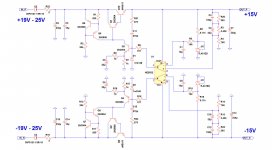
Updated schematic:

I discarded the trimmer to cut down costs and room, and replaced the Rg resistor with two resistors in parallel, to be able to "trim" my output voltage within a reasonable margin.
As for the layout: C3 and C5 shall be mounted underneath the board - I don't know whether I will use C3 yet, but C5 will be soldered directly to NE5534's power pins. The five resistors of the reference and divider part (3.3k, 47k, Rf, Rg1, Rg2) are mounted vertically. I have used a star ground scheme right at the load's ground (OUT -). No remote sensing since I don't think I can cope with potential stability issues right now. And I don't think it matters that much for my application. So, the layout:

I have attached two regulators side by side, which is the way I plan to make my pcb to minimise room needed. I will use twelve regulators, in a total length of 30cm. Each regulator section is 10cm deep. A question here, about regulators' separation: right now in this layout, minimum separation distance between tracks of two individual regulators is 0.7mm. I have used 1.5mm tracks for the heavy current path, and 1mm for all other tracks, so that is why I get 0.7mm for this given layout.
So the question is: is this separation adequate, or may I experience problems? Each regulator must be isolated from each other - they will feed 12 different loads. Should I ensure a bigger minimum separation distance? I assume that bigger can't harm, but if 0.7mm is already adequate (or 1-1.5mm, whatever) I would strongly prefer it. Reasons are cost plus size.
Updated schematic:
I discarded the trimmer to cut down costs and room, and replaced the Rg resistor with two resistors in parallel, to be able to "trim" my output voltage within a reasonable margin.
As for the layout: C3 and C5 shall be mounted underneath the board - I don't know whether I will use C3 yet, but C5 will be soldered directly to NE5534's power pins. The five resistors of the reference and divider part (3.3k, 47k, Rf, Rg1, Rg2) are mounted vertically. I have used a star ground scheme right at the load's ground (OUT -). No remote sensing since I don't think I can cope with potential stability issues right now. And I don't think it matters that much for my application. So, the layout:
I have attached two regulators side by side, which is the way I plan to make my pcb to minimise room needed. I will use twelve regulators, in a total length of 30cm. Each regulator section is 10cm deep. A question here, about regulators' separation: right now in this layout, minimum separation distance between tracks of two individual regulators is 0.7mm. I have used 1.5mm tracks for the heavy current path, and 1mm for all other tracks, so that is why I get 0.7mm for this given layout.
So the question is: is this separation adequate, or may I experience problems? Each regulator must be isolated from each other - they will feed 12 different loads. Should I ensure a bigger minimum separation distance? I assume that bigger can't harm, but if 0.7mm is already adequate (or 1-1.5mm, whatever) I would strongly prefer it. Reasons are cost plus size.
Last edited:
Thank you vey much!
Do you think that there are comparable differences between various manufacturers? STMicroelectronics vs Texas Instruments for example?
Not from my experience.
But I have always liked to put a 1uf or greater tantalum capacitor on the output of the LM317 close to the IC to reduce noise.
I would like to ask something about stability for regulators in general. If the answer cannot be general, let me specify that I refer to the Sulzer regulator I am building.
So, say I want to use a regulator for currents up to 200mA DC. That is the maximum DC current I will need, whether it is used to power a heater up or to feed a preamplifier.
Can I be sure that if I check the output using an oscilloscope, while drawing these 200mA of current (by connecting, say, a fixed resistor that will draw that much) and finding no oscillation or anything weird, that the regulator will be always stable for DC current up to 200mA? Whether these 200mA are a resistor, a preamp or what.
No, the worst case (most difficult to diagnose) is marginal stability, in which changing load current provokes bursts of oscillation in the regulator circuit, that die out after three, or thirty, or three hundred cycles of sinusoidal oscillation. Usually square wave testing is the first diagnostic tool people deploy when they go hunting for marginal stability.
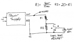
The classical test-jig for square wave testing is shown below. Vout is the output voltage of your regulator (let's pretend: 9.0 volts) and Imax is the maximum current your regulator will be called upon to provide (let's pretend: 0.2 amps). A signal generator drives fast-risetime square waves into the gate of logic-level MOSFET M1. When M1 is off, the regulator's load is (R1 + R2). When M1 is on, the regulator's load is R1. If R2 = 20*R1, the load current will vary by 21-to-1.
The classical test-jig for square wave testing is shown below. Vout is the output voltage of your regulator (let's pretend: 9.0 volts) and Imax is the maximum current your regulator will be called upon to provide (let's pretend: 0.2 amps). A signal generator drives fast-risetime square waves into the gate of logic-level MOSFET M1. When M1 is off, the regulator's load is (R1 + R2). When M1 is on, the regulator's load is R1. If R2 = 20*R1, the load current will vary by 21-to-1.
Attachments
Last edited:
Many thanks for the excellent response.
Couple of things to ask on this: first, I assume that the peak voltage of the square wave coming from the generator should be just enough the mosfet on, which means just that Vsquare,peak > Vgs for M1. Right?
Second, saying fast-risetime, I assume you mean that the generator has to provide good square waves (which will have a very good transition from low to high). Or do you imply anything about the frequency of these square waves? In that manner, it seems it is not clear to me what the frequency spectrum of this test should be.
As long as the MOSFET goes fully on and fully off, and does it quickly-enough, the test should work fine. You're just trying to bang on the circuit hard/fast-enough to see if it resonates or rings.
If the MOSFET doesn't go fully on or fully off, or doesn't get through the partially-on region fast-enough, then it will just dissipate more heat (maybe a lot more). You'd rather have it spend all of its time with Rds either very low or extremely high, to avoid i²Rds power dissipation. But that's a secondary concern, of course. You will set or vary the rise/fall times as needed and just use a bigger/better heat-sink for the MOSFET if necessary.
Frequency content should be roughly
fmax = 1 / ( π trise)
The frequencies involved in the testing usually have very little to do with the repetition rate of the pulses. The rise and fall times are where the action is.
Just to be clear, the rise and fall times are NOT supposed to be limited so that they produce only slew rates that would be found in audio signals. You just want to see what high-frequency modes might be lurking in the circuit, and eliminate or mitigate them, so that they can't possibly be elicited later, during normal operation.
If possible, I would probably slowly sweep the rise/fall times, from slow to fastest, while watching a scope or spectrum analyzer.
You could also do similar testing on the completed system, with a square wave into each audio input, in turn.
I think you would get acceptably fast risetime square waves if you built a tiny single-chip "signal generator" on your solderless breadboard / protoboard, using an NE555 timer IC. Power it from 10-18 volts, drive the MOSFET gate from pin_3 (Iout = 200mA !!), choose a MOSFET with low Qg_tot, done.
An NE555 powered from 10-18 volts produces a large amplitude square wave (I don't know about yours, but my cheapo GW Instek signal gen's square wave output is "TTL", i.e., 3 volts max swing). With a 10-18V square wave from an NE555, you can use any MOSFET, not just the logic-gate variety. The IRL510 or any of the varieties of 13N06* would work nicely. They have Qg_tot < 6.5 nC, so with 200mA driving the gate, the switching time is less than 33 nsec. Plenty fast enough. You can use the risetime bandwidth equivalency formula: BW * tr = ~ 0.34 to calculate the equivalent signal bandwidth.
*FQPF13N06, FQU13N06, FQP13N06, FQT13N06, FQD13N06, etc
Thanks for the reply Mark! Jenyok, thanks for your kind contribution of this schematic, but I have settled down to the super simple Sulzer regulator.
So I could progressively move towards 10MHz, regarding the square frequency, is that right? I mean, in that bandwith limit, the mosfet will be able to retain the fast rise time needed - correct? Apologies for my lack of testing experience.
If I use a 555, maybe it is not that handy to sweep frequencies. With a signal generator, it comes easier.
As Tom suggested earlier, rise time is of concern, so maybe a sweep is not necessary?
(A "terminology" question: when you say "drive the MOSFET gate from pin_3 (Iout=200mA !!)", I suggest you mean "give ample voltage to open the gate so that 200mA flow through the Drain", am I correct? Sometimes I just want to double check my understanding of English.)
So I could progressively move towards 10MHz, regarding the square frequency, is that right? I mean, in that bandwith limit, the mosfet will be able to retain the fast rise time needed - correct? Apologies for my lack of testing experience.
If I use a 555, maybe it is not that handy to sweep frequencies. With a signal generator, it comes easier.
As Tom suggested earlier, rise time is of concern, so maybe a sweep is not necessary?
(A "terminology" question: when you say "drive the MOSFET gate from pin_3 (Iout=200mA !!)", I suggest you mean "give ample voltage to open the gate so that 200mA flow through the Drain", am I correct? Sometimes I just want to double check my understanding of English.
)
Last edited:
So you just suggested that the 555 is able to drive demanding loads, so the gate of a MOSFET requiring actually zero current should be a piece of cake. Right?
Will go out tomorrow and search for parts, I guess! A frequency of 10kHz regarding the square wave that the 555 puts out should be a good place to start I suppose.
Will go out tomorrow and search for parts, I guess! A frequency of 10kHz regarding the square wave that the 555 puts out should be a good place to start I suppose.
No. The gate of a MOSFET is a very demanding load. Why else would semiconductor companies build "MOSFET Gate Driver" chips like the Microchip MCP1407 whose output current is a whopping 6 amperes?
(I mentioned that chip only because I used it recently in a bellringer board design)
Big MOSFETs have big Qg_tot which means they are very challenging to drive. If you're going to drive a MOSFET from an NE555 whose output current is "only" 0.2 amperes (rather than 6.0 amperes), you're going to need a MOSFET with a small Qg_tot. Use the "search" feature of your browser to find posts in this thread that mention Qg_tot.
And, just for the sake of comparison, look up the specs of your signal generator's square wave output. What is its rated output current? (This may be expressed as an output impedance instead). Calculate the switching time when your signal generator drives the gate of whichever MOSFET you're thinking about using.
To be honest, I have never used mosfets, so I had only read about the need to drive their input capacitance in a typical power amplifier. Not that this is rediculously easy, according to your post too - I may have been very crude saying "piece of cake" instead "adequately".
Thanks for the promts. At the moment, no access to instruments...hopefully I will find my way in the future, whether the future is days or months!
Thanks for the promts. At the moment, no access to instruments...hopefully I will find my way in the future, whether the future is days or months!
- Status
- This old topic is closed. If you want to reopen this topic, contact a moderator using the "Report Post" button.
- Home
- Amplifiers
- Power Supplies
- Accurate voltage regulation