Sorry but it is 2.6kw or 5kw?
Fch47n60 can be ok it is similar to the onesI proposed some time ago.
Maybe for 5kw you will need 2 in parallel or a single fch76n60. For 2.6kw
this is more than enough.
I have made a 2.4kw phase shift using 4xIXTQ480P2 with very good results. I have also tried with spw35n60cfd with similar results.
For 5kw I don't know, I have never tried something that powerful.
Btw: what is your switching frequency? You can consider lowering it a bit and using IGBT + parallel fred instead of mosfets. In a phase shift smps the bridge is soft switched and fast 600v type IGBTs can do the job better than mosfets. They are also much more easy to drive (lower Qg).
It's 5kw , transformer is an EE71 Ferroxcube , switching frequency 110KHz , that's why i mentioned fch76n60 ,for 2.6 kw there isn't any reason to use such a big mosfet ....with IGBT there is too much conduction loses , almost all the igbt have Vce>2V , plus the current tail , that means more dead time for each bridge leg , lower duty cycle and increase in switching current for the same power and the IGBT at 110Khz .....even the Fch47n60 it seems to do the job if it stays cool enought and it can handle 30A than it's ok , but if there is a short circuit and before the protection reacts , it will blow .
Btw , i didn't use DC blocking capacitor , the smps worked fine at 100 v input and 500w , even those poor mosfet's didn't heated hard without any heatsink only the rectifier diode from the seccondary .
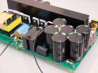
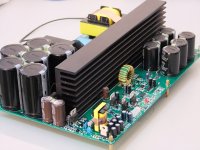
wo, EE71 and 110kHz and full bridge for 5kw, so expensive.upload our 5kw smps pics here. EE55/20 core, half bridge,90kHz. rated continous power.IGBT perfect.
Attachments
And this one will do how much? 5k?
5k right. it can delivery out more power but power limiter circuit not allow,peak value larger.due to limiter circuit limit average power.
wo, EE71 and 110kHz and full bridge for 5kw, so expensive.upload our 5kw smps pics here. EE55/20 core, half bridge,90kHz. rated continous power.IGBT perfect.
Looks gooooooddddd , but the specs are way to optimistics (my opinion ), for exemple with my core i calculated only the core loses to be 15W with 3f3 material at 110khz , plus cooper loses will reach more than 30W total, i have seen some cores e55 from ferroxcube at 5KW ,but they are cooled bu cooper fins and heatpipes (google J.KOLAR 5kw telecom power supply ) . And if it's half bridge , the primay current must be over 40A ..... anyway it looks goood!
if design hign efficiency smps ,cannot copy of the traditional textbook formulaLooks gooooooddddd , but the specs are way to optimistics (my opinion ), for exemple with my core i calculated only the core loses to be 15W with 3f3 material at 110khz , plus cooper loses will reach more than 30W total, i have seen some cores e55 from ferroxcube at 5KW ,but they are cooled bu cooper fins and heatpipes (google J.KOLAR 5kw telecom power supply ) . And if it's half bridge , the primay current must be over 40A ..... anyway it looks goood!
.half bridge resonant smps can delivery out 10kW or more in industry application.
like electric welder.if design audio amp smps, low EMI , higher energy reserve ,high efficiency and good stability are goal.
Last edited:
wo, EE71 and 110kHz and full bridge for 5kw, so expensive.upload our 5kw smps pics here. EE55/20 core, half bridge,90kHz. rated continous power.IGBT perfect.
5kw with that small transformer? hmmm
I wonder 5KW for how many seconds?
It would be great and interesting showing it loaded 3KW
EMI will be bad thing at that load without PFC
5kw with that small transformer? hmmm
I wonder 5KW for how many seconds?
It would be great and interesting showing it loaded 3KW
EMI will be bad thing at that load without PFC
At 5KW pfc must exist .
Without pfc and with a good battery of caps the current will be insane .at 250W and 1000uf without pfc the current from the mains was 15A ....
wait what? 15A? for 250w? peak?At 5KW pfc must exist .
Without pfc and with a good battery of caps the current will be insane .at 250W and 1000uf without pfc the current from the mains was 15A ....
I don't see how else you would see that... I had my with only 470uF, 2 since half bridge, 730w of pure dc and 100Hz peaks to just over 1kw... with pfc, pure dc only with no problem
It's a joke right?
Please be serious..... 5kw continuous from an ee55 sounds strange..... It was difficult for me to get 3kw from that core with forced air cooling and keep the transformer temperature below 125°C at 50°C ambient temperature....
For sure it can give that power and probably much more as peak power but for sure not as a thermally limited continuous rating.
250w without PFC;
I assume 120v input voltage. The capacitance after the rectifier sets the diodes conduction time and thus the power factor PF.
Now normally the amount of capacitance required is dictacted by the needed holdup time and the ripple current that the capacitors can whitstand.
As a rule of thumb when the voltage ripple on the capacitors is 20% of the peak rectified voltage the PF is 0.55.
Let's assume that your smps has a tremendously low efficiency of 70%.
Let's calculate the input current:
active input power: Pin=Pout/eff=357W
apparent input power: Sin=Pin/PF=650VA
input rms current: Iin=Sin/Vin=5.4A
Even if you exagerate with your input cap and degrade the PF to 0.2 (quite impossible) you will not reach 15A.
A different story is if you are speaking of peak input current with and without PFC; this can be surely quite an order of magnitude less with PFC
EMI without PFC:
it is not that without PFC the EMI will be worse; with PFC you have the EMI of the phase shift + the EMI of the PFC to filter out.
The problem is the size of the EMI filter that can withstand almost two times the current without PFC without saturating or overheating at full power.
PFC is practically mandatory for every phase shift converter (independently from its power) because to make a phase shift work properly with good efficiency its duty cycle shall be increased as much as possible to reduce the circulating current. This means that a properly designed phase shift smps can only work with a narrow input voltage range and the PFC provides a fixed voltage for the phase shift smps.
Ciao
-marco
wait what? 15A? for 250w? peak?
I don't see how else you would see that... I had my with only 470uF, 2 since half bridge, 730w of pure dc and 100Hz peaks to just over 1kw... with pfc, pure dc only with no problem
The value for the 15A is taken from a simulation made in Psim , the capacitance is 1000uF , load 290 ohms .... maybe in reality it will be lower due to components
Regard power supply , check this
http://www.hpe.ee.ethz.ch/uploads/tx_ethpublications/Optimization.pdf
http://www.pes.ee.ethz.ch/uploads/tx_ethpublications/Badstuebner_APEC10_02.pdf
http://www.pes.ee.ethz.ch/uploads/tx_ethpublications/APEC_08_Badstuebner.pdf
check the cooling system of transformer
http://www.hpe.ee.ethz.ch/uploads/tx_ethpublications/Optimization.pdf
http://www.pes.ee.ethz.ch/uploads/tx_ethpublications/Badstuebner_APEC10_02.pdf
http://www.pes.ee.ethz.ch/uploads/tx_ethpublications/APEC_08_Badstuebner.pdf
check the cooling system of transformer
TI gave me a day long lecture about quasi-resonant switch mode power supplies here in Hanoi in exchange for a cup of coffee. That is to say they gave me a cup of coffee in exchange for sitting through all that. I am easily bribed. Who knows why they were here because they won't sell to Vietnam or provide samples.
if design a smps for audio amp as telecom smps, maybe smps cost will higher than all finished amp.
because telecom smps work along, and MTBF over 200000 HOURS
must find way to realize our aim with lower cost.
Nice work , but in amps there is no 5kw continues ,anyway by the way that transformer is constructed there in no way to handle 5kW continues only at a room temperature low enough and with force air , even then the center of the core will exceed 150C .Even the winding for a 5kw E55 core is hard , very thigh wounds ,i guess cooper foil , but with this proximity effect is nasty.
Nice work , but in amps there is no 5kw continues ,anyway by the way that transformer is constructed there in no way to handle 5kW continues only at a room temperature low enough and with force air , even then the center of the core will exceed 150C .Even the winding for a 5kw E55 core is hard , very thigh wounds ,i guess cooper foil , but with this proximity effect is nasty.
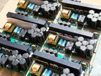
smps must have ability for full power and continuous working, like large pond.
about others parameters when design, experience is most important.we have to try it many time for one art.
very good fan cooling system necessary when full loader working.not only circuits and fan but also duct system design.
Only connected loads will prove the claimed 5KW
- Status
- This old topic is closed. If you want to reopen this topic, contact a moderator using the "Report Post" button.
- Home
- Amplifiers
- Power Supplies
- 2600w Smps