Kudos. There is a similar implementation from Stage Accompany with their SA8535. That version was horn loaded.
Sent from my Nexus 6 using Tapatalk
actualy it is nothing like the stage acompany
") they used a normal quasie ribbon type structure based on a normal loudspeaker motor they have one coil suspended in between 2 magnets. with a backplate like a normal speaker and a core. they used 2 big feriet magnets to make the field in the gap. nice design, but different. it cant go as low i think, pure tweeter use. and i wonder what reflection does with he closed backplate.
they used a normal quasie ribbon type structure based on a normal loudspeaker motor they have one coil suspended in between 2 magnets. with a backplate like a normal speaker and a core. they used 2 big feriet magnets to make the field in the gap. nice design, but different. it cant go as low i think, pure tweeter use. and i wonder what reflection does with he closed backplate. but nice design, inspirational
yea the flux lines are not well aligned with current in trace at center line of magnet runs so really probly not much difference if you use just a strip of foil with no current and you dont have to have perfect alignment with your method so easyer.
As for the speed of sound in the material, its all out the window and non linear when you add a viscous adhesive and laminate.
As for the speed of sound in the material, its all out the window and non linear when you add a viscous adhesive and laminate.
well the material is constant i believe except for parts where there foil or no foil , the rest is pretty straight forward. the calculations sort of match it. but the proof is in the pudding , i try to get rid of the suckout by increasing the membrane width and see where the new suckout is going to land. it is harder since it is not as sharp as with the high frequency, or maybe it isbut since at the lower frequency we are sort of soomed in compared to the high frequencys might put it on linear to have a better image of deep nulls.
Hmm the suck out changes with resonance , so it actually are 2 resonances one st 400 then drops off ( suckout) like it normally does after a resonance then comes up again and does the same at the overall panel resonance. I am thinking it might might be the fact that 1/2 of the membrane is covered by the baffle that holds the magnets . Usually when you close one side of an planar Esl or any other the resonance goes up , in this case since a part is open you get 2 resonances. But leaving the whole thing open will give us booming resonanting sound since it is only driven in the middle. Sooo I am going to try the following
I create either an open bAfle with just enough strength to hold the magnets , then add thick felt to either side of the active part.
Or I get a thicker bAfle and create 2 pockets 3 mm deep on either side of the active part, and will fill it with rather dense felt.
I did a small test with a smaller baffle on the bigger membrane and I seemed to extend lower . But a proper test is needed yeh iteration nr 6 or so. Still using only 16 magnets
I create either an open bAfle with just enough strength to hold the magnets , then add thick felt to either side of the active part.
Or I get a thicker bAfle and create 2 pockets 3 mm deep on either side of the active part, and will fill it with rather dense felt.
I did a small test with a smaller baffle on the bigger membrane and I seemed to extend lower . But a proper test is needed
yeh iteration nr 6 or so. Still using only 16 magnetsHeja heja - interesting testing. Even if you narrow of the actual active driver surface, will not the width of the baffle set the dispersion pattern - i.e. still not wide in this case?
//
well the active part dictates the dispersion since dispersion, is a thing higher up the frequency range, witch the active part emits most.
But i might resort to a classical design with full driving membrane to see if the suckout goes away, since it is hard to controll.
Downside is price and dispersion. the wider i make it the worse dispersion will be, but if i narrow it the resonance will be to high.. damned never ever a free lunge in audio.
i received some smaller new magnets with 30x3x2mm they are weaker but also 1/3 the price i will try to make a 150x80mm panel and try to cramp in 50 -60 magnets. i might devide the coil up into 2 or 3 parts to maybe add a lowpass to the bass section to still have some controll over dispersion.
have u tryed silicone dots? I think magneplane does something similar. not sure how to test to find the right spot / spots? Maybe hold finger lightly on diaphragm? This method may only move the suckot around though not sure
You can also try loading the diaphragm from the rear with a felt sheet or more open fabric. Best if solidly attached to lots of support like the magnets/frame..U can vary the resistance to air flow to some effect on these resonances. I think many of the modern planers have such a felt or cloth "resistor" to help tame.
small diaphragms are tough. Peaks right where u dont want and the small dimensions often make tunning and keeping that tune over time difficult.
Last edited:
have u tryed silicone dots? I think magneplane does something similar. not sure how to test to find the right spot / spots? Maybe hold finger lightly on diaphragm? This method may only move the suckot around though not sure
You can also try loading the diaphragm from the rear with a felt sheet or more open fabric. Best if solidly attached to lots of support like the magnets/frame..U can vary the resistance to air flow to some effect on these resonances. I think many of the modern planers have such a felt or cloth "resistor" to help tame.
small diaphragms are tough. Peaks right where u dont want and the small dimensions often make tunning and keeping that tune over time difficult.
yeah i used felt inside outside front and, back. i got the 60 magnets version playing. dispersion is awfull. the panels measures 145-125mm but it has a dip under 500 hz again.... they are rather efficient i must say. i filtered it with more then 9 dB down, and still it is 3 dB louder then my woofer
but i cant say i like the sound of this panel. might listen to it tomorrow at a decent level. Magnepan used a bolt with a plastic ring, what i guess they do is creating 2 resonances one to fill the gap between the lowest resonance and where the panels go louder. but it could as well be just tuning the main resonance to extend as far as possible at the required level.
Panorama Loudspeaker
not 100 % sure but I think the larger plane sections are very large area diaphragms driven by a smaller area. Undriven area well damped, long, lossy termination.
not 100 % sure but I think the larger plane sections are very large area diaphragms driven by a smaller area. Undriven area well damped, long, lossy termination.
Panorama Loudspeaker
not 100 % sure but I think the larger plane sections are very large area diaphragms driven by a smaller area. Undriven area well damped, long, lossy termination.
yes thats sort of it, but they used 3 drivers to cover the range, wich makes it easier. waaay easy. its not hard to make a middrange that big, same goes for the mid tweeter and tweeter. but expensive. i want best of both worlds i guess
Yea the problem area ( about 100-400 hz ) is done by the planer sections where only a small area of the total diaphragm is active. This is the arraignment Ive gotten the best perf from myself. Done a few different designs this way. In fact one was were the driven section was only about 25 mm wide. A short one about 100 mm long and a long 600 mm version were made. Then a few with square and rectangular active sections about size of a 5 inch cone in area. The results were all same, the undriven areas of the diaphragm are the majority of the dia area. Some had the undriven area damped by very close ( approx 2 mm) proximity board on both sides of diaphragm. Some used various materials laminated to undriven area to get damping.
Ether way I believe this is whats called a lossy transmission line termination. The pulse moves out from the active area and is absorbed by the undriven area enough so that the strong resonance doesnt build.
Onother variation was a "concentric" planer of sorts. Basically a rectagulaer diaphragm about 300mm wide by 1000 mm tall. It was a heavyer bass diapgragm panel with a light MRT running on same diapgragm right in center. MRT and bass foils actually used same magnet rows at center as well. There were serious issues BUT it was suprising how well just the MRT would play when no bass energy feed to woofer section. The woofer was basically a large suspension and damping medium for the MRT center section.
These designs I think do the best at flattening response BUT are HUGE ha
the mrt is esential a magnepan, although the possition of the tweeer is different,
my coclussion of small driven area on bigger membrane, is this, it does lower resonance, but will have 2 problems, 1 is suckout secondly without massive damping there will be a drum like sound. not nice. when all of this is damped the only benefit is lower resonances since the surface area no longer active contributes to the output.
So nice trick to lower resonance of a small panel to some extend, when damped to the max. still if you want to output with high spl the problem of excursion becomes clear. it starts to sound very compressed, maybe a push pull could counter this a bit. but i guess larger surface area lower excursion sounds better. with a neodymium setup this would be a waste of money and spl you never going to use. im still looking for a rubber magnet version.

well the reasion for the large undriven area is not to simply lower resonance but to give a much lower Q. The result when done right is a very flat response through the problem region.
This not really a new design if this what manuafcture claiming. I remember seeing a planer that was done this way years ago. It was flat to 80 hz where it rolled of smoothly.
Basically this arraingment allows the tension nessasary for good control without the harsh freq response that typicaly goes with it.
well the reasion for the large undriven area is not to simply lower resonance but to give a much lower Q. The result when done right is a very flat response through the problem region.
it still will roll off. and spl is limited to what you might expect of the same panel with the size of the active part, maybe slightly bigger but when damped right not much
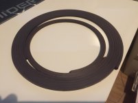
I finally bought rubber magnet and managed to cut it in half rather well. i am very pleased.
Problem was for a panel to work with rubber magnet it is not about strength so much, it is more about surface area and distribution of as much magnets as possible, i believe.
But 4 mm wide magnet made of rubber is not available anywhere so it seems. there was one time i could get 400 meters, but they sold it just before i wanted to buy it and they wont stock it again since it is not standard. well now i bought me some 8.5mmx3mm rubber magnet, only 10 meters for some tests. i thought allot about how to accurate cut it into 2 parts for the last few years. slitting with a lathe came to mind and soem more basic stuff like cutting with a knife, another problem is that when using a knife the rubber has much resistance and the deeper you go the more resistance it has, and the knife is getting dull fast.
When i got some time ill make some pictures and maybe a video on how it looks. but it is rather simple setup. i use my cnc as a stationary router with a 1mm cutter in it (would like to use a 0.5 but had a 1mm around) i cnced a piece of plastic with a groove in it the size of the magnet, then another piece of plastic comes on top of that with a hole in it for the cutter. now i feed the magnet into the groove that now more looks like a tunnel. feeding it will let the cutter cut the material always at the exact same spot and will come out of the end of the tunnel as 2 pieces. for now my accuracy was one half was 3.50-55 and the other half was 3.60. pretty damn close, since it is rubbery material.
Still some improvements to be made in reliability, i cant just put a motor on it to let it cut on its own yet.
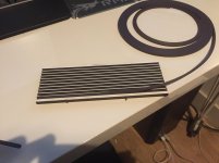
Ofcourse i made a fast panel with the frame i had from the first revisit of the poor mans magneplanar. ripped everything of and made a Jig to space the magnets evenly when glueing, works beter then putting a spacer in between.
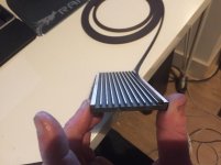
this is just lay the magnets in the right order, put glue on it and adhere to the metal and all is nicely spaced no sticky hands.
i made a single ended panel, and made some measurements, efficiency is waaay down the neo's but it plays and measures 5 ohm, i then added a push pull setup so another metal plate with the same magnets with the same pole facing the previous one. the resonance dropped 150 hz almost, some of the resonances where gone, and SPL went 6 dB up in the lowers octaves, and the high went down. wich is good , less eqing to do. only annoying thing is again a huge peak at 12khz, this time im not sure what it is. oh and i gained some distortion at 6khz , might be the membrane resonating somewhere that i cant hear but it does show up in the measurements.
Aah well it sounds rather solid right now, so a very good first try, i am happy. i can imagine making bigger panels since i only used 22 x 16cm of rubber magnet. a total of 3.5 meters (and dont forget i sliced the original magnet in 2, so actually i used 1.7 of the bought magnet.
2 of these panels could keep up with my woofer with minor eq and not giving a party
Problem was for a panel to work with rubber magnet it is not about strength so much, it is more about surface area and distribution of as much magnets as possible, i believe.
But 4 mm wide magnet made of rubber is not available anywhere so it seems. there was one time i could get 400 meters, but they sold it just before i wanted to buy it
and they wont stock it again since it is not standard. well now i bought me some 8.5mmx3mm rubber magnet, only 10 meters for some tests. i thought allot about how to accurate cut it into 2 parts for the last few years. slitting with a lathe came to mind and soem more basic stuff like cutting with a knife, another problem is that when using a knife the rubber has much resistance and the deeper you go the more resistance it has, and the knife is getting dull fast. When i got some time ill make some pictures and maybe a video on how it looks. but it is rather simple setup. i use my cnc as a stationary router with a 1mm cutter in it (would like to use a 0.5 but had a 1mm around) i cnced a piece of plastic with a groove in it the size of the magnet, then another piece of plastic comes on top of that with a hole in it for the cutter. now i feed the magnet into the groove that now more looks like a tunnel. feeding it will let the cutter cut the material always at the exact same spot and will come out of the end of the tunnel as 2 pieces. for now my accuracy was one half was 3.50-55 and the other half was 3.60. pretty damn close, since it is rubbery material.
Still some improvements to be made in reliability, i cant just put a motor on it to let it cut on its own yet.
Ofcourse i made a fast panel with the frame i had from the first revisit of the poor mans magneplanar. ripped everything of and made a Jig to space the magnets evenly when glueing, works beter then putting a spacer in between.
this is just lay the magnets in the right order, put glue on it and adhere to the metal and all is nicely spaced no sticky hands.
i made a single ended panel, and made some measurements, efficiency is waaay down the neo's but it plays and measures 5 ohm, i then added a push pull setup so another metal plate with the same magnets with the same pole facing the previous one. the resonance dropped 150 hz almost, some of the resonances where gone, and SPL went 6 dB up in the lowers octaves, and the high went down. wich is good , less eqing to do. only annoying thing is again a huge peak at 12khz, this time im not sure what it is. oh and i gained some distortion at 6khz , might be the membrane resonating somewhere that i cant hear but it does show up in the measurements.
Aah well it sounds rather solid right now, so a very good first try, i am happy. i can imagine making bigger panels since i only used 22 x 16cm of rubber magnet. a total of 3.5 meters
(and dont forget i sliced the original magnet in 2, so actually i used 1.7 of the bought magnet.2 of these panels could keep up with my woofer with minor eq and not giving a party
Attachments
Last edited:
interesting
my guess would be the acostic resistance of the second magnet on other side is damping those lower freq resonances somewhat.
I wonder if the 12k thing is due to the magnet slots cavity resonance ??
Yeah thought about the cavity to but the other magnets where also 3 mm thick. So must be the spacing between magnets, or the metal , or the fact I used one trace of 3mm ... instead of 2 of 2,8 . Highly doubt the last one.
I'm gone try one without metal. Not so sure how much strength I lose , I'll keep the same layout so I can see the difference
- Status
- This old topic is closed. If you want to reopen this topic, contact a moderator using the "Report Post" button.
- Home
- Loudspeakers
- Planars & Exotics
- The planar project :)