Looking at BGs drawings I would say their slots are approx 5mm wide, 3-4 mm deep, and about 10mm center to center between slots. Just an estimate.
their response looks to me to have a big peak at about 10-11k riding in a typically rising response.
yea I remember speaking with the designer of the Gold ribbon years ago about these type of drivers. He said getting a smooth response below 400 hz is very difficult due to the strong resonances between 100-400. And the slot resonances have to be delt with with traps. His ribbon was similar to the long BG versions so had two slots.
Also there was an article many years ago on the Strathern ribbons that are built the same way. These planers have a large undriven area at the sides. The stratherns were modded by removing the stock fiber board dampers and replacing with some light weight air filter foam. This supressed the resonances below 500 hz. Then they had to use two traps as the duel slots seemed to produce two peaks. I believe they ended up with +- 1.5 db from 300 to about 18k
An interesting side note. The stock Stratherns had a wad of fiberglass insulation tacked onto the back of the driver to taim lower freq res BUT many liked the more "open" sound with these removed dispite the technically more correct FR when in place.
Last edited:
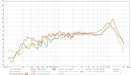
Nice info !here a measurement of an panel with 2.5mm traces and low tension vs one with high tension and 2mm traces. and one image of the first panel not in push pull.
Green single ended low tension 2.5mm wide trace
Orange same panel but in push pull with damping on front.
Red Push pull membrane with damping in front and 2mm traces.
weird enough the smaller traces although higher impedance 3.9 ohm vs 2.8 has higher output. my guess would be more of the conducting trace is into the very small 1 mm gap.
so another thing is worth trying to create a 1.5mm wide gap and see if a trace slightly larger then the 2mm of the second panel can keep up and see what happens to the peak to. field is not as strong with bigger gap, but if the trace does not fit into the gap the question is,, if a wider gap would still get more out of the traces current.
this is the reason why magnepan still uses wires. and you can get away with it in the lower end.
also nice to notice is the red panel has almost 6dB more output down low, they are exact same dimension only the tension is different and the conductor with.
also you can see the peak is pushed upwards. i wonder if you can push it so far it balances the roll off a bit.. would be nice
i am so stoked about the costs of this tiny panel") its so low it is easy to decide to fabricate another one to see what happens (although my time is not limitless)
its so low it is easy to decide to fabricate another one to see what happens (although my time is not limitless)
Green single ended low tension 2.5mm wide trace
Orange same panel but in push pull with damping on front.
Red Push pull membrane with damping in front and 2mm traces.
weird enough the smaller traces although higher impedance 3.9 ohm vs 2.8 has higher output. my guess would be more of the conducting trace is into the very small 1 mm gap.
so another thing is worth trying to create a 1.5mm wide gap and see if a trace slightly larger then the 2mm of the second panel can keep up and see what happens to the peak to. field is not as strong with bigger gap, but if the trace does not fit into the gap the question is,, if a wider gap would still get more out of the traces current.
this is the reason why magnepan still uses wires. and you can get away with it in the lower end.
also nice to notice is the red panel has almost 6dB more output down low, they are exact same dimension only the tension is different and the conductor with.
also you can see the peak is pushed upwards. i wonder if you can push it so far it balances the roll off a bit.. would be nice
i am so stoked about the costs of this tiny panel
its so low it is easy to decide to fabricate another one to see what happens (although my time is not limitless)Attachments
Last edited:
interesting that dia tension can move and shape the hi freq res.
The diaphragms tension and self damping acting against the slots dominant tune I suspect. Makes me think its kindof a helmholtz resonance ?? the air mass in the slot acting against the tension and mass of diaphragm?? maybe the volume of air between the diaphragm and mags figuring in there too??
The diaphragms tension and self damping acting against the slots dominant tune I suspect. Makes me think its kindof a helmholtz resonance ?? the air mass in the slot acting against the tension and mass of diaphragm?? maybe the volume of air between the diaphragm and mags figuring in there too??
and it continious
some moving images about what i did last week
https://youtu.be/ASutTwsJRMs
Oh i did another thing, i cleaned the panel from the solid ink and then the huge peak goes up in frequency a bit 500-800 hz, also the lower end distortion goes up a tiny tiny bit like 0.08% or so i just see changes in the distortion graph near the resonance, so i rather let the ink on it for now. first i must try to get the peak further up. i am waiting on the glue to dry on a panel with 1.5mm coil and no alumnium in between, with the neo's i got an peak and a dip when using this sort of layout, lets see if the result are the same. so i know i still have to fill up unused mylar or not
Last edited:
Ok i made one membrane with 12 micron alu instead of the 9 micron, i ordered some samples with my big roll as well of 12 and 25 micron. but the result is the same huge peak at 12khz and then drops at 15, so it has to be something with the structure, and the 12 micron is to heavy for tweeter duty i will try and make a version tomorow or day after with a wider magnet gap. like 1.5mm the field will be lower then it is now, but i would like to see something shift at least
with the neodymium i reached 18khz witch is good enough for me. so i know it should be possible.
with the neodymium i reached 18khz witch is good enough for me. so i know it should be possible.
Last edited:
anyone have an idea how to be able to calculate this type of segmentation for a planar ?
is it useing the coil and the caps as a 2 order filter ? i cant wrap my haed around it , im terible at crossovers
An externally hosted image should be here but it was not working when we last tested it.
is it useing the coil and the caps as a 2 order filter ? i cant wrap my haed around it , im terible at crossovers
I wouldnt dismiss foil heavyer than 12 micron too quickly. Some good tweeters are made with even heavyer foil. Many dont realize that the MRT used in the Apogee Stage and some others use foil closer to 17 microns.
I have built many using much lighter foil with a flatter response out to 20k , they have a certain quality BUT in all honesty my ears seem to like the heavyer foiled ones better IF all is well damped.
AND I dont like flat response at all. It sounds "Hi Fi" a well taylored roll off has always sounded more real to me.
BTW the height / width ratio of those slots, if the width is larger than the height I think you may get a better result. make the ratio as small as possable??
Last edited:
The 12 micron is only the aluminium, the substrate is for both 12 Micron polyester . So it is already on the heavy side.
Slot height is as high as the panel , so can only change width. From 1 mm to 1,5 will be first try. If the width of 1 mm is the reason for the peak, adding as much as 0,5 should change allot.
Slot height is as high as the panel , so can only change width. From 1 mm to 1,5 will be first try. If the width of 1 mm is the reason for the peak, adding as much as 0,5 should change allot.
i see the image is not working so here again
anyone have an idea how to be able to calculate this type of segmentation for a planar ?
is it useing the coil and the caps as a 2 order filter ? i cant wrap my haed around it , im terible at crossovers
anyone have an idea how to be able to calculate this type of segmentation for a planar ?
is it useing the coil and the caps as a 2 order filter ? i cant wrap my haed around it , im terible at crossovers
Attachments
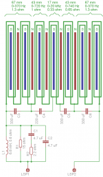
The "filter" at the input is likley a trap circuit to deal with a peak, the caps spread out within the tracings I believe are to help with dispersion by making smaller portion of diaphragm work as frequency goes up. I tryed this araingment once but was not impressed with result. also tryed "shading the array" a few times by having much stronger magnets closer to diaphragm at center of the diaphragm with magnet spacing getting larger as you approch edges of diaphragm. That one was interesting as the low freq resonances were much reduced AND the midrange was noticablt more natural, BUT senativity suffers and bass dynamics as well
Last edited:
Would like to try the trap circuit , the way magnepan deals with it is wasting power that could be used for low end. I know that there basspanels are not capable to reproduce high frequency. And the same goes for the high frequency piece can't handle the current required and has damping issues when used low . So for there design the only way to go is a crossover.
Today I found the source of my magnets yeaaah to bad for the guy in the middle but good for me . I will order a hefty amount since this is needed to get something cheap I halved the cost per meter so it's worth it I guess it's 250 meters before cutting I could make a panel or 2 I presume there is only one step up if I want it cheaper and that is knocking on the doors of the German company that produces it I believe. But they redericted me instantly to the importer in the Netherlands , so I guess I can't match there required MOQ. must be several km of the stuff well I just must be glad I got this far I think.
Now back to th design, I am going to try the wire method today , not so much because I use wire but because I can chose substrates freely like Mylar 1 3 and 6 micron , and maybe even a more lose and softer foil like pp or pe although they are not so stable as Mylar, i might even try. Kapton stil got a few meters left, nice thing is it already has adhesive on it so I might be able to stick the aluminium wire to it without having dirty fingers and such ��
I only got either realy thin wire or thick , i guess smaller with bad power handling is the best for testing
Today I found the source of my magnets
yeaaah to bad for the guy in the middle but good for me . I will order a hefty amount since this is needed to get something cheap I halved the cost per meter so it's worth it I guess it's 250 meters before cutting I could make a panel or 2 I presume there is only one step up if I want it cheaper and that is knocking on the doors of the German company that produces it I believe. But they redericted me instantly to the importer in the Netherlands , so I guess I can't match there required MOQ. must be several km of the stuff well I just must be glad I got this far I think. Now back to th design, I am going to try the wire method today , not so much because I use wire but because I can chose substrates freely like Mylar 1 3 and 6 micron , and maybe even a more lose and softer foil like pp or pe although they are not so stable as Mylar, i might even try. Kapton
stil got a few meters left, nice thing is it already has adhesive on it so I might be able to stick the aluminium wire to it without having dirty fingers and such ��I only got either realy thin wire or thick , i guess smaller with bad power handling is the best for testing
Last edited:
Well the wires where even worse. at least on kapton, kapton in this thickness is to heavy and while the adhesive provides damping it also screws up the high end and efficiency. made a new glue jig for a spacing between magnets of 1.5mm then i made some new foils, glued them and wanted to test.. but ofcourse i screwed up the layout.... damned. not feeling like doing some more etching at this time of day. so i know what i will be doing tomorrow after work. while miss aligned, there is still output, almost as much as a normal single panel, but it introduces weird phasing since you cant align all magnets well its like a in between where it peforms best. it does sound pretty open and clear, but im not sure if it is because of the wider gap, or the fact there is soem phasing going on. the sort of gimmick Dolby surround used its so spacious !
at least on kapton, kapton in this thickness is to heavy and while the adhesive provides damping it also screws up the high end and efficiency. made a new glue jig for a spacing between magnets of 1.5mm then i made some new foils, glued them and wanted to test.. but ofcourse i screwed up the layout.... damned. not feeling like doing some more etching at this time of day. so i know what i will be doing tomorrow after work. while miss aligned, there is still output, almost as much as a normal single panel, but it introduces weird phasing since you cant align all magnets well its like a in between where it peforms best. it does sound pretty open and clear, but im not sure if it is because of the wider gap, or the fact there is soem phasing going on. the sort of gimmick Dolby surround used its so spacious ! Au au au ..... my muscles hurt like hell.
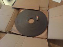
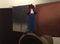
my magnets arrived its 1/3 of my body weight damned its no fun walking from the tram back to my house with it.
people looked and thought wtf are you doing its a small box how heavy can it be jesus.
there are 4 more under this top one now i got some cutting ahead..... like uhm allot
my magnets arrived its 1/3 of my body weight damned its no fun walking from the tram back to my house with it.
people looked and thought wtf are you doing its a small box how heavy can it be jesus.
there are 4 more under this top one
now i got some cutting ahead..... like uhm allotAttachments
So i did a test with dumping the metal plate, normally its good to have the magnets sit on metal to close the circuit. but my thought was the magnetic strength is so low the metal could be very thin to have still some benefit. but what happens when we completely remove it ? well i removed it from the front side and measurements are exactly the same. no losses at all. i will do the backside to, and see what happens. at least it looks way way better.
it saves on perf metal to, its not that cheap. and i can make any size i want yeeej, although my blue HPL is getting low must find myself an alternative playing material. thought about a nice black high gloss acrylic front ?
it saves on perf metal to, its not that cheap. and i can make any size i want
yeeej, although my blue HPL is getting low must find myself an alternative playing material. thought about a nice black high gloss acrylic front ?Attachments
Last edited:
Dumping the second perforated metal piece did not change anything either, if i measure up close the one with HPL instead of metal even has a straighter curve. like flat line (excet for the peak in the 12khz region).. so thats good
here is the video of the first perf plate i replaced. about the distortion, it somehow is there at a certain level. when using 2 panels in series i can match this level without the distortion. so either the panel is at her max, or my amp in 3 ohm its not the DSP and not the laptop
excuse me for saying slots almost like sluts
here is the video of the first perf plate i replaced. about the distortion, it somehow is there at a certain level. when using 2 panels in series i can match this level without the distortion. so either the panel is at her max, or my amp in 3 ohm
its not the DSP and not the laptopexcuse me for saying slots almost like sluts
Last edited:
- Status
- This old topic is closed. If you want to reopen this topic, contact a moderator using the "Report Post" button.
- Home
- Loudspeakers
- Planars & Exotics
- The planar project :)