Hi , i played around with planar magnetic speakers now for a while , all based on the cheap rubber magnet. then i stumbled onto some neodymium's with a size of 50x3x3. at first i though i would make a normal arrangement going vertical.
But in the end i simulated the magnets used without backplate from metal, and the loses are not that much. at least not enough to make it unusable so i continued.
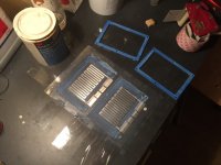
I used them vertical and the trick i wanted to try is make the memnbrane bigger then the actual magnet structure to lower self resonance without losing tension or getting it floppy. here are soem pictures of the thing and a small badly recorded video.
https://www.youtube.com/watch?v=Cyz1fZVAkRE
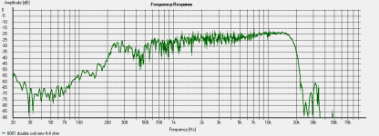
it plays here from 350 i believe, with some heavy eq to let it reach that low and eq to counter the rising frequency response.
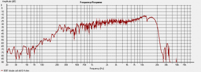
Main problems i had where strange peak and nunll at 12 khz, i finally found what it was. where the magnets are there are no traces, the traced run in between magnets. But depending on width of the piece without trace it creates a resonance. if i fill this part in with alumnium without it being connected to anything the resonance disapears. only problem is that the whole laminate is a tiny bit on the heavy side i reach 17-18khz~ not a big deal since most dont hear it but still. the laminate i used i bought a **** load of so might as well use it. would be great if i could find slightly thinner material, but i searched years to even get hold of this stuff so i wont see that happen any time soon
i made 2 (small one and a bigger one with more space in between the magnets )of these with all coils in series i get 12 ohms, so with a little tweaking it should nbe possible to do 2 coils in parallel and then the 2 panels in series. or other way around. with filtering it reaches 83 db ~ the smaller one is more efficient because the field is more consentrated but the bigger one reaches a bit lower since it has more surface area. but i think i prefer the smaller one. it will just cost some more magnets. now they home ~6 euro of magnets each.
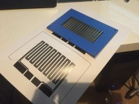
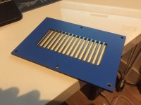
I used my cnc to make the HPL where the magnets are press fit into. no fidling around with glue or spacers etc just pop the magnets in.
My aim would be able to cross it at 250-300hz (24 or 12dB oct) or maybe higher with only a 6db passive filter if possible. if i am able to filter the top frequency passively as well.
But in the end i simulated the magnets used without backplate from metal, and the loses are not that much. at least not enough to make it unusable so i continued.
I used them vertical and the trick i wanted to try is make the memnbrane bigger then the actual magnet structure to lower self resonance without losing tension or getting it floppy. here are soem pictures of the thing and a small badly recorded video.
https://www.youtube.com/watch?v=Cyz1fZVAkRE
it plays here from 350 i believe, with some heavy eq to let it reach that low and eq to counter the rising frequency response.
Main problems i had where strange peak and nunll at 12 khz, i finally found what it was. where the magnets are there are no traces, the traced run in between magnets. But depending on width of the piece without trace it creates a resonance. if i fill this part in with alumnium without it being connected to anything the resonance disapears. only problem is that the whole laminate is a tiny bit on the heavy side
i reach 17-18khz~ not a big deal since most dont hear it but still. the laminate i used i bought a **** load of so might as well use it. would be great if i could find slightly thinner material, but i searched years to even get hold of this stuff so i wont see that happen any time soon i made 2 (small one and a bigger one with more space in between the magnets )of these with all coils in series i get 12 ohms, so with a little tweaking it should nbe possible to do 2 coils in parallel and then the 2 panels in series. or other way around. with filtering it reaches 83 db ~ the smaller one is more efficient because the field is more consentrated but the bigger one reaches a bit lower since it has more surface area. but i think i prefer the smaller one. it will just cost some more magnets. now they home ~6 euro of magnets each.
I used my cnc to make the HPL where the magnets are press fit into. no fidling around with glue or spacers etc just pop the magnets in.
My aim would be able to cross it at 250-300hz (24 or 12dB oct) or maybe higher with only a 6db passive filter if possible. if i am able to filter the top frequency passively as well.
Attachments
Last edited:
I'd be very interested in an in-depth build using the cheap rubber magnets, link please?
I would love to , but I had an opportunity to buy 500 meters of th stuff. But did not have money for it back then. 1 week ago I told them I would want buy the 500 meters, but they sold it already and since there is not enough demand for them they are not going to stock it again.
I asked for help a few times here on the forum to do a group buy , but no response so ... I will look for a new supplier and when I do I might even get the neodymium version although 3 or 4 times as expensive the field is 4 times stronger to witch can help.
The rubber magnet still is high on my list for several reasons
1. Need more surface area , this can cheaply be achieved with rubber.
2. Since the surface area is bigger it can reach lower.
3. Push pull can be achieved without spending huge amounts of money.
4. Not dangerous building a push pull with neodymium scan be dangerous and hard to get together
5. no fancy tools needed just scissors and glue
6. Costs costs costs. 1 meter 4x3 mm could be as cheap as 1-2 euro these neos are 6-7 euro a meter
If anyone still would like to share costs for custom made magnet from china Or local let me know. A batch in the Netherlands would cost 1000 plus
In the video i crosser them that low but I did mentioned some heavy eq to do so. I recon to use 2. Panels at least or make them bigger. I don't have an spl meter the only guide I got is the very inefficient 5 inch tangband sub. I recon the double panel is around 83 db with filtering the high frequency rise. (Without it it would be much much higher) Distortion is hard to measure at the moment since I don't trust my new laptop and I font have and comparison at the moment . What I got was around 0,2-0,4 percent in rew. And the lower you go the higher distortion becomes. When I got it all sorted out I should make some decent ( so up close since I want to eliminate noise and the room)
So i made a new membrane for the smallish driver. im pretty pleased with the result, might need to damp the resonance a bit more.
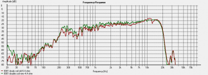
With the new layout frequency response is better and efficiency as well since it has lower impedance. Most noticeable is the top end i mentioned about not having aluminum in between the traces creating some weird peaks and nulls (seen in the old one, was even worse in the first few types i made), here it is fixed.
I might need to increase the DC spacing or damp the resonance since it makes some ugly vibrating noises when a sweep is played at high level(think it hits the magnet structure). This happens near the resonance, or down low where excusrion becomes higher and higher.
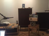
in the picture you can see the distance i measured it, its more then 1 meter. and SPL wise after filtering the high frequency downwards with 8 dB he is still 3-4 dB louder then the woofer. but then again that woofer is as efficient as i am with money.
1e measurement is the old membrane RAW no smoothing or EQ
2e is the new one RAW no smoothing or EQ
3e is old and new with 24db oct smoothing. no EQ
4e is setup
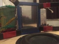
5e is a closeup of the shiny membrane, and the woofer playing behind it
i play with it now crossed at 250, this is doable as long as you dont send sine waves with high power, because i did not damp the resonance this will result in ugly noises, but just casual music is no problem.
as you can see i screwed up the placing of the coil vertically in the right spot, so had to realign it, but now the frame does not match... aah well its just a concept ofcourse.
oh one last thing i always have this NULL at 400 Hz, and i got no clue what it is (maybe distance to wall or whatever). i many times tried to eq it but i think it is something in my room or so, because all measurement of every panel have this problem.
With the new layout frequency response is better and efficiency as well since it has lower impedance. Most noticeable is the top end i mentioned about not having aluminum in between the traces creating some weird peaks and nulls (seen in the old one, was even worse in the first few types i made), here it is fixed.
I might need to increase the DC spacing or damp the resonance since it makes some ugly vibrating noises when a sweep is played at high level(think it hits the magnet structure). This happens near the resonance, or down low where excusrion becomes higher and higher.
in the picture you can see the distance i measured it, its more then 1 meter. and SPL wise after filtering the high frequency downwards with 8 dB he is still 3-4 dB louder then the woofer. but then again that woofer is as efficient as i am with money.
1e measurement is the old membrane RAW no smoothing or EQ
2e is the new one RAW no smoothing or EQ
3e is old and new with 24db oct smoothing. no EQ
4e is setup
5e is a closeup of the shiny membrane, and the woofer playing behind it
i play with it now crossed at 250, this is doable as long as you dont send sine waves with high power, because i did not damp the resonance this will result in ugly noises, but just casual music is no problem.
as you can see i screwed up the placing of the coil vertically in the right spot, so had to realign it, but now the frame does not match... aah well its just a concept ofcourse.
oh one last thing i always have this NULL at 400 Hz, and i got no clue what it is (maybe distance to wall or whatever). i many times tried to eq it but i think it is something in my room or so, because all measurement of every panel have this problem.
Attachments
Last edited:
If distorsion is under control I think you have something going here.
//
yeah and i have some troubles measuring that. distorting also measured at 1 meter ? since that is gone suck inside a room i think
oh about the NULL , it might be suckout from the resonance at 220 looks like the null is exactly at 440. ill try dampen it see what happens
I have been able to measure what seems to be reasonably distorsion values in-room. But go closer by all means - say 20 cm. But see to that the levels at least correspond to to say 85 dB 1 meter.
//
ok, will try that, might need an spl meter to set for 85-90, as far as i can see now it has relative high 2e order distortion, kind of weird. with damping i can get the lower frequency down allot, but im far from being there, i think i need some more surface area to relief the tiny membrane a bit. i have it playing music now crossed at 250 with only a 12db oct filter and heavy eq to make up for the low end. as much as 14 dB, would be nice to be able to straighten that up a bit. and relief it from over driving to compensate for the losses down low
nice job WrineX. I see youve found out that covering the entire diaphragm with foil is better than foil only between magnets. This is absolutly tru and I would advise to make the current carrying traces wide enough to cover as much diaphragm as possable rather than using an undriven strip of foil. You wont loose any sensativity even though some foil will not be in the best magnet flux .
As for your null at 400. It may be room BUT planers tend to have serious issues between about 150 and 400 usually with around 200 being the worst. Often if the light is just right you can see the standing waves ! Damping these is tricky, fix one create another. Apogee has done the best here IMO.
I have noticed with my own planer designs that symmetry of the driven area tends to amp up these resonances. If you look at the Apogee bass panel you see they did not place the magnet array symmetrically in the panel. There is a fair amount of empty undriven space. This can help taime some of the resonant activity but it tends to soften dynamics just a bit. Still well worth it in the midrange.
The smoothest plane Ive made had a diaphragm about 10 inches wide BUT the magnet array was only about 4 inches wide and just off center a little. the undriven areas all around the driven area act as a well matched damping section absorbing some energy before it reflects off the frame and back into the diaphragm. Sort of a lossy transmission line termination. This undriven area covered with same foil and adhesive as traces of course (better damped than just the film this way). It had a very smooth ribbon like midrange BUT lost bass dynamics.
.As for your null at 400. It may be room BUT planers tend to have serious issues between about 150 and 400 usually with around 200 being the worst. Often if the light is just right you can see the standing waves ! Damping these is tricky, fix one create another. Apogee has done the best here IMO.
I have noticed with my own planer designs that symmetry of the driven area tends to amp up these resonances. If you look at the Apogee bass panel you see they did not place the magnet array symmetrically in the panel. There is a fair amount of empty undriven space. This can help taime some of the resonant activity but it tends to soften dynamics just a bit. Still well worth it in the midrange.
The smoothest plane Ive made had a diaphragm about 10 inches wide BUT the magnet array was only about 4 inches wide and just off center a little. the undriven areas all around the driven area act as a well matched damping section absorbing some energy before it reflects off the frame and back into the diaphragm. Sort of a lossy transmission line termination. This undriven area covered with same foil and adhesive as traces of course (better damped than just the film this way). It had a very smooth ribbon like midrange BUT lost bass dynamics.
Last edited:
Thanks lowmass, yeah I was worried about the traces coming near the middle of the magnet where the flux is switching to the other side. About filling in the rest with al was my idea as wel although I tried this already , iT givea probleem neT the erge of the spacers and vibraties so i need to leave a fee mm without al. About the standing waves thuis is Bert trie, the filking of the space between the traces is aan example of this. The thing is it works with the speed of sound waves in the polyester not in the air I think that's why a space of 3 mm resulted in a problem around 12 kHz . In air a size that would matter would be 344/12000 0,02866 / 2 = 0,0144 meter half a wave length. On the membrane it looks like 3 mm is giving problems at this frequency 14,4 mm / 3 mm = 4,8
Hmm so 344 meters / 4,8 = 71,6
If we now use this speed for a gap op 3 mm it's 71,6/12000 = / 2 (for half a wave length) = 0,002983 meter x 1000 to get mm = 2,98 mm
Let's see what I get for the 430 hz problem
71,6 / 430 hz / 2. =0,083 meter or 83 mm. This is rather close to the width of the membrane , I am not at home so I can't look it up but this might something to look in to .
One more example I made one membrane with leaving 2,6 mm bare foil between traces. The annoying peak followed by a dip (as seen in previous picture old membrane red trace) at around 13 kHz
When I calculate it this comes out 71,6/0,0026 / 2 = 13700 hz again pretty close. This is crusisl information I think , this way I know to eliminate resonances I must keep unsupported Mylar under 1,7 man if I want resonances out of the pass (300) band membrane must have a width/height above 11,9 cm . I'm gone check all this theorie when I am home and can take a better look at the measurements.
Last edited:
Thanks lowmass, yeah I was worried about the traces coming near the middle of the magnet where the flux is switching to the other side. About filling in the rest with al was my idea as wel although I tried this already , iT gives problems near the edge of the spacers and vibraties so i need to leave a few mm without al. About the standing waves this is Very true, the size of the space between the traces is an example of this. The thing is it works with the speed of sound waves in the polyester not in the air I think that's why a space of 3 mm resulted in a problem around 12 kHz . In air a size that would matter would be 344/12000 0,02866 / 2 = 0,0144 meter half a wave length. On the membrane it looks like 3 mm is giving problems at this frequency 14,4 mm / 3 mm = 4,8
Hmm so 344 meters / 4,8 = 71,6
If we now use this speed for a gap op 3 mm it's 71,6/12000 = / 2 (for half a wave length) = 0,002983 meter x 1000 to get mm = 2,98 mm
Let's see what I get for the 430 hz problem
71,6 / 430 hz / 2. =0,083 meter or 83 mm. This is rather close to the width of the membrane , I am not at home so I can't look it up but this might something to look in to .
One more example I made one membrane with leaving 2,6 mm bare foil between traces. The annoying peak followed by a dip (as seen in previous picture old membrane red trace) at around 13 kHz
When I calculate it this comes out 71,6/0,0026 / 2 = 13700 hz again pretty close. This is usefull information I think , this way I know to eliminate resonances I must keep unsupported Mylar under 1,7 mm if I want resonances out of the pass (300hz) band membrane must have at least a width/height above 11,9 cm . I'm gone check all this theorie when I am home and can take a better look at the measurements.
Ah i looked up the width of the panel and according to this
"Let's see what I get for the 430 hz problem
71,6 / 430 hz / 2. =0,083 meter or 83 mm"
my panel is exactly 83mm wide
one last thing i wondered about is i assumed sound would propegate faster in the foil then in air but with all these calculations i used 71.6 meter/sec instead of 344 in air. so that would indicate slower...
thats why the wavelength gets shorter by 4.8 times.
Last edited:
Ah i looked up the width of the panel and according to this
"Let's see what I get for the 430 hz problem
71,6 / 430 hz / 2. =0,083 meter or 83 mm"
my panel is exactly 83mm wide
i sound like on of these guys that think 9/11 where due to aliens or something
- Status
- This old topic is closed. If you want to reopen this topic, contact a moderator using the "Report Post" button.
- Home
- Loudspeakers
- Planars & Exotics
- The planar project :)