Ok then, if you have time.... take the photos of your soldering job, nice and close @ reasonably high resolution, and post here for the board of experts to examine, and provide feedback")
Replaced the JFET's though the older ones were perfectly fine. replaced the ZTX's & now hell's broken loose, both the offset and the bias have started swinging...what did I break now

Pictures is a problem, freejaz are you using Taptalk for uploading pics, my system doesn't seem to support
I was running this by Jim and he hinted (Jim, I hope that was a hint) that I post my problem here, so...
I'm having a similar problem to kpsthakur. I can adjust the offset on the good (left) side to 0. When I try to adjust the bad (right) side nothing happens and I have a static voltage of approximately -21.45 v. On the good board I can adjust the bias to 350 mv. On the bad side I can adjust the bias to 350 mv. So the problem appears to be related to the offset is some way.
I've checked the values of the parts and everything appears to have the correct orientation and location. Photos are attached. Any suggestions?
There is no bias current running through the MOSFET's; the output is floating at -V. The MOSFET's are not conducting. Everything I posted before, applies to your case/your issue as well. Voltage drops across R7 and R8 are critical; so is the voltage across Q4 (between collector and emitter, the 4.3V one...). That's pretty much all you need to worry about.
Last edited:
There are two types of ZTX's used in Aleph J, make sure that the appropriate type goes where it is supposed to go; double-check. The BJT's CAN be checked with an ohmmeter/diode tester, accurately, (as opposed to JFET's) so it's worth checking that as well.
Yup, ZTX550 in the middle, the 450's on either end. Checked..
I’ve checked the orientation and position of the small transistors and they now seem to be ok. I have not pulled them out since then to test them as I have no idea which ones to test first. I’m also assuming that I can only pull them out and put them back in so many times before they fail. Is there a more specific suggestion? Thanks
I’m using the diyaudio uploader.
I’m using the diyaudio uploader.
Last edited:
Yup, ZTX550 in the middle, the 450's on either end. Checked..
Ok, then re-check the soldering. It seems that you've already found issues with it... before...
I’ve checked the orientation and position of the small transistors and they now seem to be ok. I have not pulled them out since then to test them as I have no idea which ones to test first. I’m also assuming that I can only pull them out and put them back in so many times before they fail. Is there a more specific suggestion? Thanks
I’m using the diyaudio uploader.
If you are not ready (willing/do not know how) to pull the transistors out to check... then the only thing left is to replace one at the time and hope for the best.
I was running this by Jim and he hinted (Jim, I hope that was a hint) that I post my problem here, so...
I'm having a similar problem to kpsthakur. I can adjust the offset on the good (left) side to 0. When I try to adjust the bad (right) side nothing happens and I have a static voltage of approximately -21.45 v. On the good board I can adjust the bias to 350 mv. On the bad side I can adjust the bias to 350 mv. So the problem appears to be related to the offset is some way.
I've checked the values of the parts and everything appears to have the correct orientation and location. Photos are attached. Any suggestions?
I would reflow the soldering, there does appear to be some very poor solder joints. Don't be afraid of the heat. Applying a good hot soldering iron to both sides of each joint for 2-3 seconds will allow the solder to flow freely. I always wipe all the leads with fine grade emery paper before soldering to remove any oxidization.
Last edited:
Iv'e had a bit of an issue with my AJ build??....all good, 24v rails, bias 0.550mv up't it over 1.5 hours to this (5U case) and offset as good as zero as you would get. Left ift on the bench for another hour rechecked wo ho...all good. Put it into service in the work shop system good for about another hour, checked sink temps...45c all looking good...then pop. +20vdc on the spk out on one board.

After some investigation I found that one of the j74s (one of the matched quads) had decided to become a resistor. I have know Idea why...the Peak tester says there a short defective component.
Its partner is fine..

I replaced both 74s with new and all is now well...DIY all good fun..errr
After some investigation I found that one of the j74s (one of the matched quads) had decided to become a resistor. I have know Idea why...the Peak tester says there a short defective component.
Its partner is fine..
I replaced both 74s with new and all is now well...DIY all good fun..errr
Last edited:
Pass DIY Addict
Joined 2000
Paid Member
That's odd... I've never read of anyone running into this type of jFet failure before. How long have you been up and running since your repair? Are you sure that you've actually found the source of the problem and that the dead jFet isn't just a symptom of a problem elsewhere?
That's odd... I've never read of anyone running into this type of jFet failure before. How long have you been up and running since your repair? Are you sure that you've actually found the source of the problem and that the dead jFet isn't just a symptom of a problem elsewhere?
Yes very odd, it was on the bench for a about 3 hours after repairs, all OK up to 45c at which point I had another project to progress. In truth I replaced all the 'active' components 450s, 550, zener, etc just to make sure as the original components may have taken some abuse...but they all tested OK. All the resistors and caps checked out OK.
I'm confused too....and will investigate further. It is strange as both of the boards were built side by side component by component..but I could of easily missed something simple.
Pass DIY Addict
Joined 2000
Paid Member
One possibility - perhaps you have a bur on one of your heatsinks that was grounding against your output mosfets? Just a guess... I've done this more times than I care to admit and is the primary reason that I now use ceramic aluminum oxide insulators with grease instead of any type of silpad. This might explain why the problem occurred only after some time at temperature.
If things are working - then leave well enough alone. If the problem happens again, I'd check your mosfet mounting sites.
If things are working - then leave well enough alone. If the problem happens again, I'd check your mosfet mounting sites.
I would reflow the soldering, there does appear to be some very poor solder joints. Don't be afraid of the heat. Applying a good hot soldering iron to both sides of each joint for 2-3 seconds will allow the solder to flow freely. I always wipe all the leads with fine grade emery paper before soldering to remove any oxidization.
Which ones are “very bad”? I’ve already reflowed every single one holding for 3 seconds so this surprises me. Can you mark up a photo? Thanks
Another Aleph J Comes to Life
Hey All,
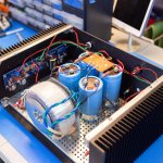
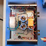
Long time lurker and first time poster. I built this amp last August and finally had some free time to take some pics. This amp was my first DIY build and definitely not my last.
The 4U case is just big enough for everything. I went through several iterations of the power supply's layout. The 90 degree bracket is a recent addition and was most helpful making space for the filter caps. The power supply is probably oversized: 600VAC transformer with 60,000uf caps. I may try the universal board with a 300VAC transformer one day, but I'm afraid the amp won't have as much shove as it does.
Sound quality is excellent and outperforms my brand name amps. I pair the amp with Zu Omen Dirty Weekend's and Monitor Audio Silver 6's.
There is a slight hum in both channels with the Zu's. The hum gets louder when I move the input wires closer to the center of the amp as well as the wires carrying +/-24V DC .
Any suggestions on better wiring layout would be greatly appreciated!
-Rusty
Hey All,
Long time lurker and first time poster. I built this amp last August and finally had some free time to take some pics. This amp was my first DIY build and definitely not my last.
The 4U case is just big enough for everything. I went through several iterations of the power supply's layout. The 90 degree bracket is a recent addition and was most helpful making space for the filter caps. The power supply is probably oversized: 600VAC transformer with 60,000uf caps. I may try the universal board with a 300VAC transformer one day, but I'm afraid the amp won't have as much shove as it does.
Sound quality is excellent and outperforms my brand name amps. I pair the amp with Zu Omen Dirty Weekend's and Monitor Audio Silver 6's.
There is a slight hum in both channels with the Zu's. The hum gets louder when I move the input wires closer to the center of the amp as well as the wires carrying +/-24V DC .
Any suggestions on better wiring layout would be greatly appreciated!
An externally hosted image should be here but it was not working when we last tested it.
An externally hosted image should be here but it was not working when we last tested it.
-Rusty
Attachments
- Home
- Amplifiers
- Pass Labs
- Aleph J illustrated build guide