Hi all,
I finally (almost) finished my X-BOSOZ/ONO preamp. It seems to work fine (on the scope) but there are a few unexpected (by me) things that make things a bit complicated.
I´m using a balanced stepped volume control wich works very well when I measure the balanced output (with an unbalanced input and -in connected to ground).
Problems start when I only measure the +out to ground (unbalanced out). Here the volume control has a very weird influence on the output signal. It does nothing at very high attenuation settings, then in the midrange reduces the output signal and then finally seems to be working ok.
I can change this behaviour by connecting -out to ground through one of the volume controls 1k2 resistors. Then it works as it is supposed to be.
Can someone explain this behaviour? Can it be cured by using current sources instead of resistors?
The complicated part I was talking of before involves comparisson with my old (unbalanced) preamp. I would have liked to do this unbalanced and balanced so I could test it with my Aleph and with my Crescendo amps. It would also be nice to use the same cables and see if a Kimber PBJ (balanced) beats a Kimber select (unbalanced).
When it stays like it is now I will be changing quite a few things when changing preamps and can only use the Aleph.
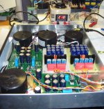
Here are two pictures of the (almost) finished X-BOSOZ/ONO.
The first is the power supply with Pquadrats boards for the ONO and 4 x 60VA transformers (2 x 2x30V and 2 x 2x60V).
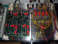
The second is the preamp again with pquadrats Ono boards and a veroboard X-BOSOZ. The cases are not finished yet and no led is working........
william
I finally (almost) finished my X-BOSOZ/ONO preamp. It seems to work fine (on the scope) but there are a few unexpected (by me) things that make things a bit complicated.
I´m using a balanced stepped volume control wich works very well when I measure the balanced output (with an unbalanced input and -in connected to ground).
Problems start when I only measure the +out to ground (unbalanced out). Here the volume control has a very weird influence on the output signal. It does nothing at very high attenuation settings, then in the midrange reduces the output signal and then finally seems to be working ok.
I can change this behaviour by connecting -out to ground through one of the volume controls 1k2 resistors. Then it works as it is supposed to be.
Can someone explain this behaviour? Can it be cured by using current sources instead of resistors?
The complicated part I was talking of before involves comparisson with my old (unbalanced) preamp. I would have liked to do this unbalanced and balanced so I could test it with my Aleph and with my Crescendo amps. It would also be nice to use the same cables and see if a Kimber PBJ (balanced) beats a Kimber select (unbalanced).
When it stays like it is now I will be changing quite a few things when changing preamps and can only use the Aleph.
Here are two pictures of the (almost) finished X-BOSOZ/ONO.
The first is the power supply with Pquadrats boards for the ONO and 4 x 60VA transformers (2 x 2x30V and 2 x 2x60V).
The second is the preamp again with pquadrats Ono boards and a veroboard X-BOSOZ. The cases are not finished yet and no led is working........
william
Attachments
Hi Raka,
thank you. Yes the first half sounds. I´m just listening to a more or less crippled X-BOSOZ (unbalanced in, unbalanced out) on my upstairs equipment.
Even in this state the sound is a lot better than expected , verry detailed, good room information width and dept. Before I listen downstairs I have to activate the ONO part and the source selector relais.
The only problem I have is the smell of the resistors.....it smells like someone is ironing shirts with a very hot iron. I hope this´ll go away after a while.
william
Amo,
the transformers are from a local manufacturer www.tauscher-transformatoren.de. They are not really cheap but very good quality. I also ordered the tranformers for my Aleph-X from them. Their 600VA is just as big and heavy as a 900VA from another supplier.
It seems that you can specify the VA rating in a lot of ways.....
william
Hi Hugo,
well it is kind of solved. Balanced operation is ok and for unbalanced I must connect the negative output resistor to ground.
My problem was more in understanding why the volume control has such a funny effect when using only one phase and if this behaviour can be changed by using current sources instead of resistors.
william
second test
well,
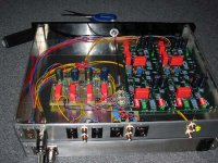
I´ve finally wired up everything (see picture below) and although it looks a bit messy for my taste everything seems to be working ok. Source selection is improvised with an external switch cause the final selectors will be in the top of the case wich is not ready yet. I´ve installed a blue led inside the case to keep everyone happy.......
I hooked it up to my main system yesterday and had a bit of a listen wich I repeated today. Most listening was done with a balanced connection (Kimber PBJ) to my Aleph5. Comparissons are always relative to my previous preamp (a tuned elektor "the preamp" with OPA627/637, Elma ladder, Pan. FC, big power supply etc.)
First impressions are not that bad.
There´s absolutely no humm or noise with cd or phono sources.
The midrange is very nice and natural sounding with a good detail (enhances the effct the Aleph had).
Soundstage is ok but not really special. Performers are not as 3D as I´m know them.
The bass also sound very natural with good detail but is a bit soft and seems to be a bit down in level (here I must check if my balanced attenuator in combination with the 10muF output caps don´t make a nice highpass).
The highs are also very detailed and fast but can be a bit grainy sometimes.
Listening to the ONO there´s a further loss of bass and the highs are a bit too much (like too much VTA) but I suspect that it needs a few more hours before it´s fully burned in so I´ll comment on that a bit later.
I think I will listen a few more days before I will start finishing the cases (the tops need lots of holes for cooling) and fronts.
Will keep you informed
well,
I´ve finally wired up everything (see picture below) and although it looks a bit messy for my taste everything seems to be working ok. Source selection is improvised with an external switch cause the final selectors will be in the top of the case wich is not ready yet. I´ve installed a blue led inside the case to keep everyone happy.......
I hooked it up to my main system yesterday and had a bit of a listen wich I repeated today. Most listening was done with a balanced connection (Kimber PBJ) to my Aleph5. Comparissons are always relative to my previous preamp (a tuned elektor "the preamp" with OPA627/637, Elma ladder, Pan. FC, big power supply etc.)
First impressions are not that bad.
There´s absolutely no humm or noise with cd or phono sources.
The midrange is very nice and natural sounding with a good detail (enhances the effct the Aleph had).
Soundstage is ok but not really special. Performers are not as 3D as I´m know them.
The bass also sound very natural with good detail but is a bit soft and seems to be a bit down in level (here I must check if my balanced attenuator in combination with the 10muF output caps don´t make a nice highpass).
The highs are also very detailed and fast but can be a bit grainy sometimes.
Listening to the ONO there´s a further loss of bass and the highs are a bit too much (like too much VTA) but I suspect that it needs a few more hours before it´s fully burned in so I´ll comment on that a bit later.
I think I will listen a few more days before I will start finishing the cases (the tops need lots of holes for cooling) and fronts.
Will keep you informed
Attachments
high pass
as I feared my choise of output caps wasn´t the luckiest.
The 10 muF together with the 1k2 output resistors give a nice highpass with a -3dB point of 30Hz and -1dB at 100Hz. So first I will up the resistors to 2k2 and the caps to 20muF.
This still will fit on the veroboard and give -1dB at 30Hz and -3dB at 9Hz. If this still doesn´t work I will have to use something like BG N 47muF like in Henriks schematic (wich fits even better )
william
as I feared my choise of output caps wasn´t the luckiest.
The 10 muF together with the 1k2 output resistors give a nice highpass with a -3dB point of 30Hz and -1dB at 100Hz. So first I will up the resistors to 2k2 and the caps to 20muF.
This still will fit on the veroboard and give -1dB at 30Hz and -3dB at 9Hz. If this still doesn´t work I will have to use something like BG N 47muF like in Henriks schematic (wich fits even better
)william
5Hz
Just measured the amp into a 27k load on a medium volume setting and it goes down to around 5Hz without any attenuation
So my theorie with the highpass filter was clearly wrong!
Could it be that since the output cap is inside the feedback loop the amp compensates the attenuation? (the original diagramm is in Henkriks X-BOSOZ thread)
What I notice is an increase in distortion towards very low frequencies (just looking at the scope).
Is it true that if I change the output caps for bigger ones, the feedback doesn´t have to compensate that much and the distortion will get less?
any help would be appreciated
william
Wuffwaff,
Is your X BOSOZ otherwise in design as per Hendricks?
I am not 100% sure but if you are only using the + out, the - out should be connected to ground via the - side of your attenuator.
In another post Hendrick posts some graphs on the X BOSOZ that may give some clues to its performance.
Ian
Is your X BOSOZ otherwise in design as per Hendricks?
I am not 100% sure but if you are only using the + out, the - out should be connected to ground via the - side of your attenuator.
In another post Hendrick posts some graphs on the X BOSOZ that may give some clues to its performance.
Ian
Ian,
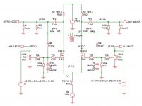
yes the design is the same. I´m using IRF510, +- 60Volt regulated supply and 680R resistors for around 40mA of bias.
The only difference is that my input is a fixed 27k to ground (input impedance) and that I use a balanced attenuator at the output.
This has a series resistor in every output ( plus and minus), and shunts restistors between those to get the wanted attenuation.
The advantage of this is that it is perfectly balanced and you only need one 24 position selector per channel. This way there are only two resistors in the signal path and one between + and -.
Balanced operation is this way. For unbalanced operation the negative out is coupled to ground via the series resistor.
I´ve just changes the series resistors from 1k2 to 2k2 and the output caps from 10muF to 20 muF. I will let it burn in for a day or so and then try it again downstairs.
william
Hi William!
Some nice amp you have made, real nice work, PCB and all.
I have compared my xbsoz directly to an bsoz and an NLE, and xbsoz is better in all parameters in my oppinion.
It seems you are not quite satified with the sound, and as you mention, some brakein might correct this.
But one thing is comming into my attention, and that is your attenuator that shortens the output at your xbsoz. As I recall, Mad_K (or some one else) tried this way of attenuation and was not at all satisfied, that is why he went back to use attenuation to ground as I also did. So this coud a be part of your problem.
The output caps (C101 and C102) passes through the lower inverted frequencies, and then they will be fed back through the resistors (R122 and R123) and then attenuate the noninverted input as much as the shunt resistors (R120 and R121) allows. But at some point on the frequensy scale, the cap (depending at the value) will begin to act as a resistor, the higher the frequensy the higher the resistance becomes, and hereby lowering the feedback acordingly. But when the NFB is lowered the gain at the drain raises, but lowered again by the resistance of the outputcap, and thus the gaindvice keeps the gain close to constant within a wider band of frequencies. As long as the cap let some current flow through the feedbackresistors (R122 and R123) the gaindevice will compensate for the lack of gain, until the maximun gainlevel of the gaindevice is reached. From there the frequensy responce falls at the output.
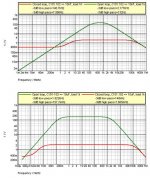
If you look at the attached file, the upper and the lower graphs shows the gain as amplitudes at different frequencies in open and closed loop (open loop is when R122 an R123 is disconnected, not shorted). The difference in closed (red curves) and open loop (green curves) tells us how much feedback we have at various frequences. When we compares the feedback in the system with 10nF and 10uF we can see that the amounts of feedback at different frequencies isn´t constant, with 10nF we barely have a band of frequencies with equal feedback which is the case with the 10uF output caps. If the only thing we had to worry about ware the frequensy response of the entire circiut, then the 10nF woud be okay. But since the X depends on the amount of feed back, we want to keep the feedback as constant as possible regardless af the frequency, so ideally we want the frequensy response in openloop mode to stay within the useually limits for high end audio, -3db 1Hz to 100 kHz, only this way we keep the X constant through out the whole audio band. So when we look at the lower curves we see that 10uF at 1K load is on the safe X-side with regard to the high pass capabability. But the low pass is a not so idal, and that is caused by the gatecapacitance of the gaindevices, wich is IRF610. If I were to do some more recearch on the Xbsoz I woud try to see if this is a problem or not, one way ore the other.
You mentioned in an earlier post, that you are using IRF510. Under normal circumstances, as in bosoz, that would be more than ok. But may be they have a little too high gate capacitance, which could strain the highend responce.
Some nice amp you have made, real nice work, PCB and all.
I have compared my xbsoz directly to an bsoz and an NLE, and xbsoz is better in all parameters in my oppinion.
It seems you are not quite satified with the sound, and as you mention, some brakein might correct this.
But one thing is comming into my attention, and that is your attenuator that shortens the output at your xbsoz. As I recall, Mad_K (or some one else) tried this way of attenuation and was not at all satisfied, that is why he went back to use attenuation to ground as I also did. So this coud a be part of your problem.
Yes.So my theorie with the highpass filter was clearly wrong!
Could it be that since the output cap is inside the feedback loop the amp compensates the attenuation?
The output caps (C101 and C102) passes through the lower inverted frequencies, and then they will be fed back through the resistors (R122 and R123) and then attenuate the noninverted input as much as the shunt resistors (R120 and R121) allows. But at some point on the frequensy scale, the cap (depending at the value) will begin to act as a resistor, the higher the frequensy the higher the resistance becomes, and hereby lowering the feedback acordingly. But when the NFB is lowered the gain at the drain raises, but lowered again by the resistance of the outputcap, and thus the gaindvice keeps the gain close to constant within a wider band of frequencies. As long as the cap let some current flow through the feedbackresistors (R122 and R123) the gaindevice will compensate for the lack of gain, until the maximun gainlevel of the gaindevice is reached. From there the frequensy responce falls at the output.
If you look at the attached file, the upper and the lower graphs shows the gain as amplitudes at different frequencies in open and closed loop (open loop is when R122 an R123 is disconnected, not shorted). The difference in closed (red curves) and open loop (green curves) tells us how much feedback we have at various frequences. When we compares the feedback in the system with 10nF and 10uF we can see that the amounts of feedback at different frequencies isn´t constant, with 10nF we barely have a band of frequencies with equal feedback which is the case with the 10uF output caps. If the only thing we had to worry about ware the frequensy response of the entire circiut, then the 10nF woud be okay. But since the X depends on the amount of feed back, we want to keep the feedback as constant as possible regardless af the frequency, so ideally we want the frequensy response in openloop mode to stay within the useually limits for high end audio, -3db 1Hz to 100 kHz, only this way we keep the X constant through out the whole audio band. So when we look at the lower curves we see that 10uF at 1K load is on the safe X-side with regard to the high pass capabability. But the low pass is a not so idal, and that is caused by the gatecapacitance of the gaindevices, wich is IRF610. If I were to do some more recearch on the Xbsoz I woud try to see if this is a problem or not, one way ore the other.
You mentioned in an earlier post, that you are using IRF510. Under normal circumstances, as in bosoz, that would be more than ok. But may be they have a little too high gate capacitance, which could strain the highend responce.
Attachments
Hello Henrik,
thanks for you reply. I´m happy I was right about the caps in the feedback loop.
The IRF510 have 135pF input capacitance opposed to 170 for the 610. This was why I choose them.
When I use the amp single ended the minus out is connected to ground via the 2k2 resistor and the volume control is just like a normal pot referenced to ground. I switched a few times between balanced and unbalanced (wich goes with the flick of a switch when connected to the Aleph5) but there wasn´t much between them. I will try this again next time.
The amp is funktioning again now with 20muF (2x10 WIMA MKS4) and 2k2 output resistors. I´ve listened to it the last hour (upstairs) and I think the problems are gone now (will confirm that when I´ve listened downstairs).
I´m still finishing the cases so it´ll be a while before I can post some new pictures. Worked a few hours today to make some holes in the top and machine the axle/bearing for the volume control.
thanks again!
William
Hi William
Data from International Rectifire:
IRF510 Ciss=180pF
IRF610 Ciss=140pF
Maybee some other brands have other specifications.
I am looking foreward to read about your "downstairs listening", I have also heard that should be the best way. and to se some pictures of the finished amp.
Regards.
Data from International Rectifire:
IRF510 Ciss=180pF
IRF610 Ciss=140pF
Maybee some other brands have other specifications.
I am looking foreward to read about your "downstairs listening", I have also heard that should be the best way.
and to se some pictures of the finished amp.Regards.
Henrik,
the 510´s are from Harris, the 135pF is from their Datasheet.
Frequency response is good, -1dB @ 100kHz and -3.6dB @200kHz so this is probably no problem.
Oh and I read your explanation again and before anyone gets confused, the resistance of the output cap gets lower the higher the frequence is........R = (1/(2*PI*f*C)
william
- Status
- This old topic is closed. If you want to reopen this topic, contact a moderator using the "Report Post" button.
- Home
- Amplifiers
- Pass Labs
- X-BOSOZ first tests