"Adding a resistor across the speaker loads the amplifier more heavily"
So I think i did have it right but perhaps didn't write it fully enough?
V=I/R
Putting a resistor in parallel with the driver (an 4/8ohm resistor in effect) reduces the overall resistance at the speaker end dropping the volts but allowing increase in the amps flowing through the circuit?
Amps (not volts) control the strength of the magnetic field generated by the voice coil?
If you put an 8ohm resistor on the back of an 8ohm driver you'd need turn the volume pot up up to a point where it outputted double the amps being fed from the amplifier to move the driver with the same strength as previously?
Whereas putting a resistor inline with the speaker would increase the resistance to current flowing from the amp? You'd need more volts (to "push") Like trying to drive with the handbrake on?
Sorry if this I common knowledge/ easy stuff for a lot of people. I'm trying to bridge the gap between knowing what individual components do and how they work together in an Audio setup.
At the moment electronic kits for me are like Lego with a soldering iron. I've been a draughtsman for 15years doing lots of Piping and Instrumentation schematics and I was a welder for a good few years too so following plans and soldering things together is childs play for me and good fun but understanding why I've done it has to be the next step.
Understanding this stuff is what the ACA is about as well as the hands on building experience.
View attachment ohms.pdf
Steve Luck
Maybe my scribbles can help out. The explanations are for resistivity circuit only DC.
Impedance is another name for resistance in an AC circuit and is complicated by capacitance and inductance to the frequency high/low in the circuit which is in the audio. P=IE power equals amps times volts. Using the arrow method arrow down say the I by half and you have half of the original P in watts, but something else would have to happen also for that to happen at the same time. Resistance in the circuit would have to had changed. It would have to have doubled to drop half of the current. Using the arrow method is generalizations but helps to understand what may be going on. I hope others can look at this and if what I say is incorrect please correct it. It has been 35 years since tech school. Have trouble uploading file. Hope it shows up. Thanks
Cool - thanks - working through these now:View attachment 726043 Steve Luck
Maybe my scribbles can help out. The explanations are for resistivity circuit only DC.
Impedance is another name for resistance in an AC circuit and is complicated by capacitance and inductance to the frequency high/low in the circuit which is in the audio. P=IE power equals amps times volts. Using the arrow method arrow down say the I by half and you have half of the original P in watts, but something else would have to happen also for that to happen at the same time. Resistance in the circuit would have to had changed. It would have to have doubled to drop half of the current. Using the arrow method is generalizations but helps to understand what may be going on. I hope others can look at this and if what I say is incorrect please correct it. It has been 35 years since tech school. Have trouble uploading file. Hope it shows up. Thanks
YouTube
Might help others too.
Putting a resistor in parallel with the driver (an 4/8ohm resistor in effect) reduces the overall resistance at the speaker end dropping the volts but allowing increase in the amps flowing through the circuit?
Remember that 'how much the voltage drops' is entirely dependent on the amp in question. For the ACA 'it drops a lot', for a typical class AB amp it might drop by only a fraction, perhaps barely measurable.
Amps (not volts) control the strength of the magnetic field generated by the voice coil?
The two are inextricably linked. If you apply 8 volts across 8 ohms you have 1 amp flowing. If you say you have 1 amp flowing in 8 ohms then you must have 8 volts across the 8 ohm load (all other things being equal).
If you put an 8ohm resistor on the back of an 8ohm driver you'd need turn the volume pot up up to a point where it outputted double the amps being fed from the amplifier to move the driver with the same strength as previously?
Sort of, its just the way of expressing it that's a bit unconventional
") More correctly we would just say that you need to turn the volume up to maintain the same voltage level at the amplifier output terminals. The amplifier doesn't so much 'output current', rather the load draws current dictated by the output voltage (and the value of the load).
More correctly we would just say that you need to turn the volume up to maintain the same voltage level at the amplifier output terminals. The amplifier doesn't so much 'output current', rather the load draws current dictated by the output voltage (and the value of the load).Whereas putting a resistor inline with the speaker would increase the resistance to current flowing from the amp? You'd need more volts (to "push") Like trying to drive with the handbrake on?
That's it.
When we talk of 8 ohm speakers and 4 ohm speakers etc, are you aware that this is a nominal value and that the actual impedance of a speaker varies enormously with frequency.
In other words an 8 ohm speaker could appear to the amplifier as perhaps a load as low as 3 ohms at some frequencies and maybe as high as 20 or 30 ohms at others.
This is what I was showing in the image earlier, it was showing how much a speaker can alter the output voltage of the ACA. An 8 ohm (or 4 ohm or 16 ohm) resistor used as a load would have given a flat response, constant output at all frequencies. The speaker load 'pulls' and 'pushes' the ACA's output all over the place because of the finite (and relatively high) output impedance of the amp.
Cheers Mooly - and happy New Year
"In other words an 8 ohm speaker could appear to the amplifier as perhaps a load as low as 3 ohms at some frequencies and maybe as high as 20 or 30 ohms at others"
This bit is evident in my DIY speakers not much load on the main amp. The Lowther DX4's being driven from a valve amp max of 9 watts output with present configuration. I run it with additional resisters on the volume pot to attenuate the signal some more and gain control of the volume a bit.
The subwoofers used to fill in the bottom octaves are driven from a signal split from the speaker cables driving the Lowthers. The split is fed into 100watt Hypex amps that need their volume turned up quite a bit to match the levels from the horns. I'm driving the horns from the ACA (and feeding the subs) while the valve amp is in the repair shop.
I pair up my ACA bridged MonoBloc with a Yamaha WXC-50 streamer preamp, however at the volume is near max at normal listening.
So i end up going thru a BA3FE before ACA....
Just sharing...
And how does the sound compare with & without the pre-amp if you match the volume ?
Sorry to hear that. To get you started:-
All the threads are M3 (3mm).
To mount the PCBs, you need 2 x 6 or 7mm brass stand offs, 2 x 6mm (short) socket head Allen screws to fit them and 2 small washers.
To mount the MOSFETS you need 4 x 10mm socket head Allen screws, 4 penny washers (fender washers) and 4 spring washers.
To mount the XLR socket you need 2 x 10 or 12mm cross head screws, 2 spring washers and 2 nuts. Black if it bothers you.
Alan
Alan,
Thanks this exactly what I was looking for.
David.
Think it's abit distorted at max volume with WXC50 alone.
Sounds alot better when i switch it to line out then thru BA3FE pre.
So my WCX50 now works as a modern input selector with optical audio from Smart Tv and streamer musiccast capabilty. Back end is BA3FE with monobloc ACA.
Sounds alot better when i switch it to line out then thru BA3FE pre.
So my WCX50 now works as a modern input selector with optical audio from Smart Tv and streamer musiccast capabilty. Back end is BA3FE with monobloc ACA.
R3 and R4 lead meltdown
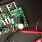
Just assembled ACA v1b. As photo shows, R3 and R4 got very hot and leads melted. When power originally applied was easily able to adjust bias to 10V. Heat rise in heat sink was moderate and output devices pretty cool. At four minutes allowing to heat, both amplifiers began smoking. Removed power (19V laptop supply). It appears one of the smaller transistors would need to have failed to over exert the R3 and R4? Search results here didn't yield postings of the same problem so I could use a little help.
Just assembled ACA v1b. As photo shows, R3 and R4 got very hot and leads melted. When power originally applied was easily able to adjust bias to 10V. Heat rise in heat sink was moderate and output devices pretty cool. At four minutes allowing to heat, both amplifiers began smoking. Removed power (19V laptop supply). It appears one of the smaller transistors would need to have failed to over exert the R3 and R4? Search results here didn't yield postings of the same problem so I could use a little help.
Attachments
Just assembled ACA v1b. As photo shows, R3 and R4 got very hot and leads melted. When power originally applied was easily able to adjust bias to 10V. Heat rise in heat sink was moderate and output devices pretty cool. At four minutes allowing to heat, both amplifiers began smoking. Removed power (19V laptop supply). It appears one of the smaller transistors would need to have failed to over exert the R3 and R4? Search results here didn't yield postings of the same problem so I could use a little help.
First congratulations on getting post #7000 on this thread and #400 on the v1.5 thread, sorry no prizes though
Second, that is a rather odd fault.
I am surprised there was enough current to melt R4's lead, was it soldered in correctly? In the picture only R3 looks burned, but R4 is lifted and does not look burned and you say both amplifiers have the same problem.
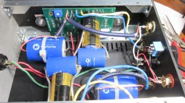
Can you post better pictures? Of the boards and the whole assemblies so we can see the components and wiring? And are the components from the kit or from other sources?
Alan
Last edited:
The overheating fault points to a problem around Q3. Make absolutely certain that R7, R8 and R15 are the correct values.
All things being equal, no fault around Q1 (even if it was dead short) would cause this. Q2 and Q3 (plus parts connected to them) are pretty much self contained in forming a current source.
As mentioned above, make sure the parts are genuine and what they say they are.
All things being equal, no fault around Q1 (even if it was dead short) would cause this. Q2 and Q3 (plus parts connected to them) are pretty much self contained in forming a current source.
As mentioned above, make sure the parts are genuine and what they say they are.
They probably are burning, just less noticeably so than the others.
Being slightly higher value (0.68 vs 0.47 ohm) means there is a very large difference in power dissipation between the two, for example at 4 amps per resistor, the dissipation is 7.5W in the 0.47 ohm and almost 11W in the 0.68 ohm.
Power is calculated as 'I squared' or 'V squared' which means seemingly small actual differences make a big difference to the actual result.
DOH, brain fa*t here this morning. Note to self: R3 and R4 are both 0.68 ohms.
(Don't know why I had imagined that one was 0.47 and the other 0.68 in parallel.)
Yes, the 'I squared' I understood too...
I had better wait till the OP posts some more info and pictures.
(Don't know why I had imagined that one was 0.47 and the other 0.68 in parallel.)
Yes, the 'I squared' I understood too...
I had better wait till the OP posts some more info and pictures.
Last edited:
Parts substitutions
I just wanted to post the results of my monoblocks build with alternative piece parts. Some of these were chosen from my parts bin, others purchased new.
-4.7uf/400V ClarityCap MR film bypass caps
-2200uf/63V Audio Note Kaisei bipolar electrolytics, bypassed with .33uf/630V ClarityCap MR.
-Welwyn RC55Y 15ppm 1/4W resistors
-Rio Grande .999 dead soft silver round wire, 20awg for signal and 3x 20awg for power and binding posts.
-Parts Connection Connex/DH Labs BL Ag bulk IC
I don't have the stock kit parts to compare it to, but it sounds fantastic. Interestingly, there is no sound of the 2200uf AN 'lytics charging at startup.
Attachments
Last edited:
Sorry, I posted in error.
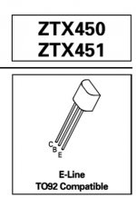
Q3 (ZTX 450) has the printing on the "rounded side". I suspect this may have been installed backward but can't test in the circuit. I have a few more of these devices from the same source so I will dig those out and see if I am able to test on my DMM (not sure I can as I've only used BJT devices in the past).
Q3 (ZTX 450) has the printing on the "rounded side". I suspect this may have been installed backward but can't test in the circuit. I have a few more of these devices from the same source so I will dig those out and see if I am able to test on my DMM (not sure I can as I've only used BJT devices in the past).
- Home
- Amplifiers
- Pass Labs
- Amp Camp Amp - ACA