Missing hardware in ACA 1.6
Hi Everyone.
I am just now getting to building my ACA and discovered that the hardware bag with the screws and washers was missing from my kit.
Can someone here post a list of the parts to see if I can find them at my local hardware store. Thanks for any help you can provide.
David.
Hi Everyone.
I am just now getting to building my ACA and discovered that the hardware bag with the screws and washers was missing from my kit.
Can someone here post a list of the parts to see if I can find them at my local hardware store. Thanks for any help you can provide.
David.
A definite maybe.
Any and all wild-*** guesses appreciated.
It is a guess at best: But may be the inputs and outputs are out of phase with respect to each other and cancelling more and more as you raise the volume?
Same concept as a karaoke machine. You knock one side out 180 with the other and match them and the voice disappears. When one side or the other is no longer equal amplitude it gets really ugly sounding.
Since the amp cards: all work on their own. I would poke a sine wave into your contraption there and look at the two speaker posts: with a scope. If they are not reversed in phase and equal in amplitude - reverse one of the inputs. In my mind, you could do that by simply moving your output resistor to the opposite side. That is to say take it from the amp on the right and feed it to the amp on the left rather than how it appears in your drawing.
Tim

Notice the resistor uses the output of the "2nd" channel and feeds it to the first.
Your drawing shows that resistor feeds the output of the first channel to the input of the second channel.
I *think* the resistor was meant to be the other way. Else you would get two in phase outputs rather than opposing outputs.
Tim
Last edited:
Hi Everyone.
I am just now getting to building my ACA and discovered that the hardware bag with the screws and washers was missing from my kit.
Can someone here post a list of the parts to see if I can find them at my local hardware store. Thanks for any help you can provide.
David.
I was missing hardware too.
I just brought a heatsink with me and found what I needed. I used the assembly manual to figure out what I needed.
bridged - augmented in voltage domain
paralleled - augmented in current domain
higher ohmic value load demands more voltage
lower ohmic value load demands more current
A nice, concise description.
I wish the manual for the ACA was a bit more clear on this for us amp newbies.


Hi Everyone.
I am just now getting to building my ACA and discovered that the hardware bag with the screws and washers was missing from my kit.
Can someone here post a list of the parts to see if I can find them at my local hardware store. Thanks for any help you can provide.
David.
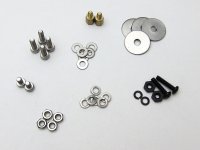
Sorry to hear that. To get you started:-
All the threads are M3 (3mm).
To mount the PCBs, you need 2 x 6 or 7mm brass stand offs, 2 x 6mm (short) socket head Allen screws to fit them and 2 small washers.
To mount the MOSFETS you need 4 x 10mm socket head Allen screws, 4 penny washers (fender washers) and 4 spring washers.
To mount the XLR socket you need 2 x 10 or 12mm cross head screws, 2 spring washers and 2 nuts. Black if it bothers you.
Alan
Attachments
well , considering how much Stuff of DiyA is paid for their work , they certainly did more than tremendous job
not mentioning how much IP and all work behind is paid for
in fact , ACA coverage is great , even if one need to go through lengthy thread(s)
+1
Question on temperatures.
I have two ACAs (1.6) setup in Parallel Input mode to get 18W at 4 Ohms. They are running hot - 122F at the heatsink face, 115F at the heatsink tip-of-a-fin. Looks like 150F is the max for the JFETS. (Running KEF LS50.)
Too hot you think?
In bridged mono, they ran 95F all day, even running AR-3a, which are 4 Ohm.
I think I'll go back to bridged.
Thoughts?
Question on temperatures.
I have two ACAs (1.6) setup in Parallel Input mode to get 18W at 4 Ohms. They are running hot - 122F at the heatsink face, 115F at the heatsink tip-of-a-fin. Looks like 150F is the max for the JFETS. (Running KEF LS50.)
Too hot you think?
In bridged mono, they ran 95F all day, even running AR-3a, which are 4 Ohm.
I think I'll go back to bridged.
Thoughts?
Not sure why they show different temperatures? Class A is Class A?
Anyway 122 degrees F is only 50 degrees C. Mine runs at 53 to 57 degrees C.
Junction temp max for the IRFP240 is 150 degrees C and the 2SK170 is 125 degrees C (257 degrees F), so you have plenty of 'headroom'!
Do not worry, Alan
Not sure why they show different temperatures? Class A is Class A?
Anyway 122 degrees F is only 50 degrees C. Mine runs at 53 to 57 degrees C.
Junction temp max for the IRFP240 is 150 degrees C and the 2SK170 is 125 degrees C (257 degrees F), so you have plenty of 'headroom'!
Do not worry, Alan
Gah! I was not paying attention - thought is was a max of 150F, which I though was way too low.
Thanks!
Not sure why they show different temperatures? Class A is Class A?
Anyway 122 degrees F is only 50 degrees C. Mine runs at 53 to 57 degrees C.
Junction temp max for the IRFP240 is 150 degrees C and the 2SK170 is 125 degrees C (257 degrees F), so you have plenty of 'headroom'!
Do not worry, Alan
Class A is class A, sorta. In Bridged mode, the voltage is doubled, but the amperage is not. In Parallel Bridged, the amperage is doubled, but the voltage is not. More "flow", small "tube" = more heat (roughly).
Use loading resistors?
Zu Audio has started selling speaker loading resistors because some amps may sound better with lower impedance. I am planning to pair the ACA with a pair of Zu Audio Omen Dirty Weekends which have a nominal impedance of 12ohms. The impedance curve is fairly dynamic. I’m wondering if the Amp Camp amp is better suited for 4-8ohm speakers and/or flatter impedance curves. I’m also trying to understand how one would know (from an electrical standpoint). And then, if the ACA / Zu Audio pairing would benefit from some resistors in series, how much resistance? What characteristic impedance should I target for an ACA? Any downsides?
I’m a total novice and am trying to learn. Thanks!
25 Ohm Speaker Loading Resistors | Zu Audio (And they have 10 and 5ohm, too)
See the charts on this page.
Bonus question: what’s the difference between characteristic impedance and nominal impedance?
I'd like to understand this too - if you put a resistor across the back of the speaker terminals that would reduce the volts or current going through to the voice coil/s and the load on the amplifier but the ACA is a low power amp - don't the voice coils on the speaker need as much volts/current as you can give them?
I ask basic questions all the time and learn lots by doing so
Cheers
Steve
Adding a resistor across the speaker loads the amplifier more heavily.
The ACA has a relatively high output impedance which means it is affected by loading, and this is seen as a change in the output voltage. The more common Class AB amps and Chip Amps behave more like a true voltage source which means that the amplifier is able to maintain its output terminal voltage as you load it.
Adding further resistance to the ACA simply reduces its available peak output voltage.
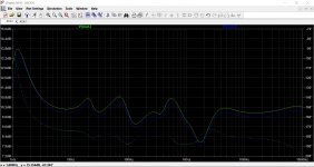
This (simulation) shows an ACA driving a real speaker load (B&W703). The voltage across the speaker terminals really does vary this much because of the ACA's high output impedance. The green trace is the speaker alone and the blue trace after adding a parallel 25 ohm. You can see it reduces the level across the board as expected.
Although 25 ohms makes only a small difference, my advice would be not to do this.
The ACA has a relatively high output impedance which means it is affected by loading, and this is seen as a change in the output voltage. The more common Class AB amps and Chip Amps behave more like a true voltage source which means that the amplifier is able to maintain its output terminal voltage as you load it.
Adding further resistance to the ACA simply reduces its available peak output voltage.
This (simulation) shows an ACA driving a real speaker load (B&W703). The voltage across the speaker terminals really does vary this much because of the ACA's high output impedance. The green trace is the speaker alone and the blue trace after adding a parallel 25 ohm. You can see it reduces the level across the board as expected.
Although 25 ohms makes only a small difference, my advice would be not to do this.
Attachments
I think the 25 ohm resistors are more aimed at high output impedance tube amplifiers, some of which can have an output Z as high as 8 ohms. In this case you effectively lower the output impedance of the amplifier to 8 parallel with 25 ohms or 6.1 ohms. This could be useful for gaining more control over the woofer resonance and also reducing the change in output voltage with frequency that results from the changing speaker impedance interacting with the amplifier output impedance. Going to an even lower resistance on the 4 ohm tap of a tube amp may be even more effective. With the ACA it won’t make as much difference, as demonstrated in the graph above.
It’s very simple to try this for yourself. You don’t need big power resistors like those shown. Given the low average power you are putting out from an ACA into an efficient speaker you could take 1/2watt 27 ohm resistors, put them across your speaker input terminals and have a listen. If 1/2 watt makes you nervous, parallel or series up a few resistors to get 25 ohms at a higher rating. It’s a cheap tweek to try.
It’s very simple to try this for yourself. You don’t need big power resistors like those shown. Given the low average power you are putting out from an ACA into an efficient speaker you could take 1/2watt 27 ohm resistors, put them across your speaker input terminals and have a listen. If 1/2 watt makes you nervous, parallel or series up a few resistors to get 25 ohms at a higher rating. It’s a cheap tweek to try.
aca likes high impedance speakers
odamone, you may achieve better sound by putting small resistor in series with speaker, not in parallel
nelson has few articles on his firstwatt site, read about current sources
That could be a valid approach for a higher powered amplifier. For the few watts that an ACA can output you will run out of voltage pretty quickly if trying to convert it to a current source using a series resistor. I think values in the 47ohm range were used in the first watt article.
you may achieve better sound by putting small resistor in series with speaker, not in parallel
This makes more sense - series, not parallel should make a difference.
- Home
- Amplifiers
- Pass Labs
- Amp Camp Amp - ACA